Suspension arm welding and positioning device and method

A welding positioning and boom technology, applied in auxiliary devices, welding equipment, auxiliary welding equipment, etc., can solve the problems of increased transfer time, high purchase cost, and large workshop space occupation, so as to improve positioning accuracy and efficiency, avoid Potential safety hazards and the effect of improving machining accuracy

Active Publication Date: 2013-05-01
ZOOMLION HEAVY IND CO LTD
View PDF9 Cites 10 Cited by
  • Summary
  • Abstract
  • Description
  • Claims
  • Application Information

AI Technical Summary

Problems solved by technology

[0007] (1) It is necessary to put the welded boom on the platform, draw the baseline and processing line for gold processing, and the marking will cause errors, and the boom must be hoisted on the platform and turned over and then hoisted off the platform, which increases the transfer time and There are security risks
[0008] (2) After the boom is welded, it must be processed by a large metal processing machine tool with an upward stroke of more than 6 meters, and there must be a special fixture on the machine tool to fasten it. In addition, it takes a long time to clamp, position and adjust the workpiece , and it is easy to cause the problem of unstable quality of product gold processing, and the efficiency is very low
[0009] (3) Large-scale gold processing machine tool equipment is not only expensive to purchase, but also high in subsequent use and maintenance costs, and occupies a large workshop space, which greatly increases the cost of boom manufacturing

Method used


Image

  • Suspension arm welding and positioning device and method
  • Suspension arm welding and positioning device and method
  • Suspension arm welding and positioning device and method

Examples


Embodiment Construction

[0035] The embodiments of the present invention will be described in detail below with reference to the accompanying drawings, but the present invention can be implemented in many different ways defined and covered by the claims.

[0036] As a first aspect of the present invention, there is provided a welding positioning device for a boom, which can be adapted for basic boom welding.

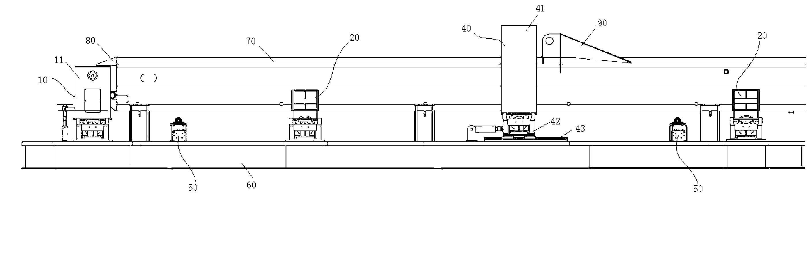
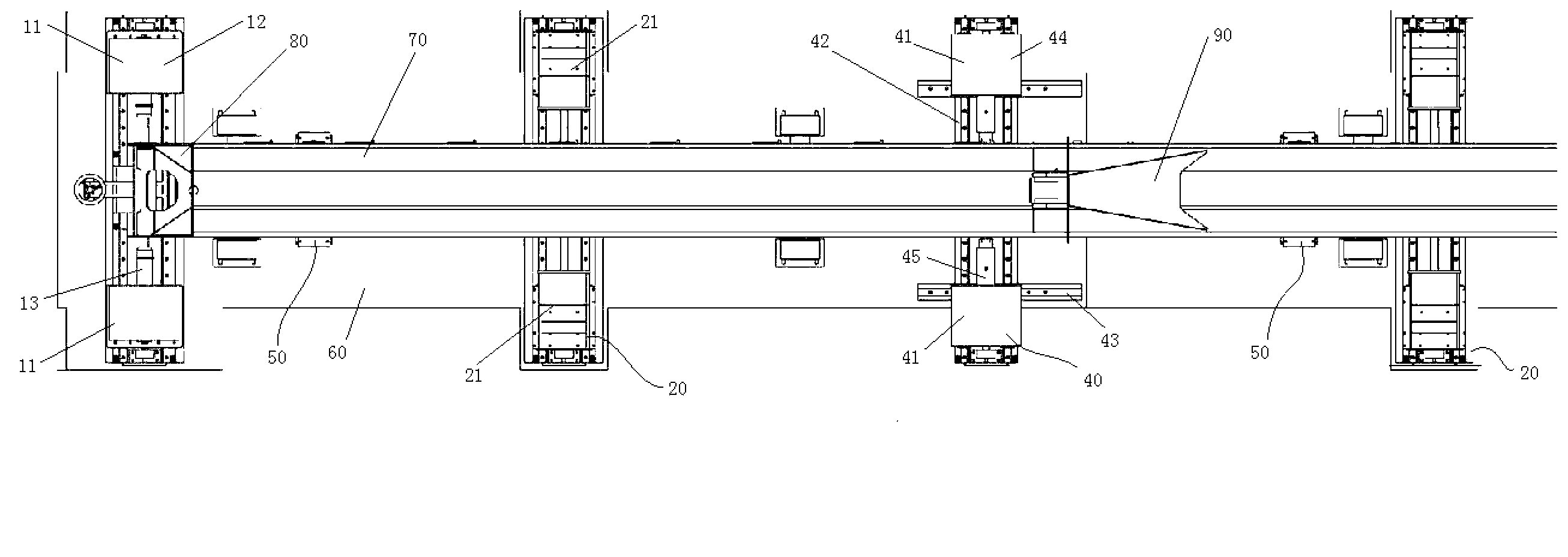
[0037] Such as Figure 2 to Figure 4 As shown, the welding positioning device includes: a tail positioning unit 10, including two tail positioning parts 11, the distance between the two tail positioning parts 11 is adjustable, and a tail positioning clamp is formed between the two tail positioning parts 11 Space; the barrel positioning unit 20 includes two splints 21 , the distance between the two splints 21 is adjustable, and a barrel positioning and clamping space is formed between the two splints 21 .

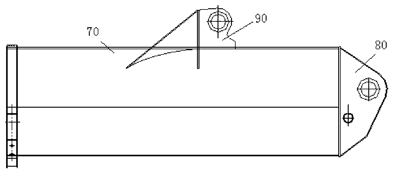
[0038] During welding, the boom tail 80 that has been processed in advance is clamped in ...


PUM


Abstract

The invention provides a suspension arm welding and positioning device and method. The welding and positioning device comprises a tail part positioning unit and a barrel positioning unit, wherein the tail part positioning unit comprises two tail part positioning parts; distance between the two tail part positioning parts is adjustable; a tail positioning and clamping space is formed between the two tail part positioning parts; the barrel positioning unit comprises two clamping plates, wherein distance between the two clamping plates is adjustable; and a barrel positioning and clamping space is formed between the two clamping plates. Because the tail part of the suspension arm is subjected to metal working and the tail part of the suspension arm and the barrel of the suspension arm are both positioned, the whole suspension arm does not need to be ruled after welding is finished. Therefore, a processing error due to ruling is avoided, the processing precision is improved, and potential safety hazards due to rotation during ruling are avoided.

Description

technical field [0001] The invention relates to the field of cranes, in particular to a welding positioning device and method for a boom. Background technique [0002] At present, the boom production of cranes (especially truck cranes) has become a bottleneck restricting the improvement of crane manufacturing efficiency. In addition, the booms in the prior art (such as basic booms, etc.), especially the improvement of the efficiency of the gold processing process, have also become a bottleneck restricting the production of booms. [0003] figure 1 A schematic structural diagram of a basic arm of a truck crane arm in the prior art is shown. Such as figure 1 As shown, the boom includes a boom tail 80, a boom barrel 70 and a luffing cylinder support 90, wherein the boom tail 80 is welded to one end of the boom barrel 70, and the luffing cylinder support 90 is welded to the boom cylinder 70. [0004] The manufacturing process of the boom in the prior art is as follows: Afte...

Claims


Application Information

Patent Timeline
Patent Type & Authority Applications(China)
IPC IPC(8): B23K37/04
Inventor 龙美花胡桂平李纲
Owner ZOOMLION HEAVY IND CO LTD
Why Eureka
Try Eureka