Building construction steel bar connection structure and connection method

A technology of building construction and connection method, which is applied in the direction of building components, building structure, construction, etc., can solve the problems of unsuitable prefabricated concrete structure and complicated construction, and achieve easy construction quality assurance, saving construction funds, and reliable connection structure Effect

Active Publication Date: 2013-05-01
HUBEI YUHUI NEW BUILDING MATERIAL
View PDF2 Cites 12 Cited by
  • Summary
  • Abstract
  • Description
  • Claims
  • Application Information

AI Technical Summary

Problems solved by technology

[0002]In cast-in-place concrete structures, mechanical connection methods such as lap joints, welding connections or extruded sleeves are often used to connect steel bars, among which lap joints of steel bars are the most Simple, the construction of mechanical connections such as welded connections or extrusion sleeves is more complicated, but these traditional construction methods must complete the connection of steel bars before pouring concrete, and are not suitable for prefabricated concrete structures.

Method used


Image

  • Building construction steel bar connection structure and connection method
  • Building construction steel bar connection structure and connection method
  • Building construction steel bar connection structure and connection method

Examples


Embodiment 1

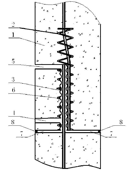
[0030] A method for connecting steel bars in building construction, the method adopts an anchorage lap joint to realize the connection of steel bars after pouring concrete, including the following steps:

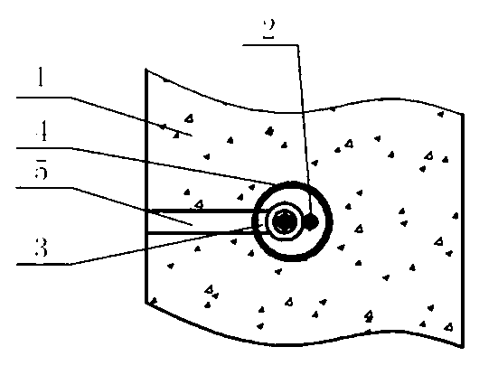
[0031] (a) Pre-embed the first longitudinal steel bar and the second longitudinal steel bar when prefabricating the concrete shear wall;

[0032] (b) A number of holes are set on the precast concrete shear wall members to form the first longitudinal hole in a reserved manner, wherein the first longitudinal hole is located near the bottom of the first longitudinal reinforcement and is basically parallel to the first longitudinal reinforcement, and the second The longitudinal reinforcement is inserted into the first longitudinal hole;

[0033] (c) Form a shrinkage gap perpendicular to the first longitudinal hole in a reserved manner, and seal the surroundings of the shrinkage gap with cement mortar;

[0034] (d) Reinforcing ribs are provided around the first longitudinal hole...

Embodiment 2

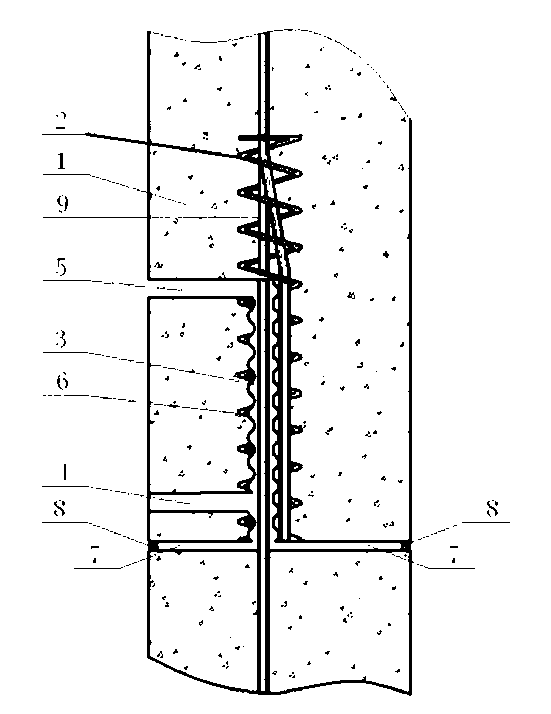
[0039] In another embodiment, other parts are the same as in Embodiment 1, except that in the step (b), the second longitudinal reinforcement is inserted into the first longitudinal hole and directly anchored to the first longitudinal reinforcement. Lap connection: the lower part of the first longitudinal reinforcement is bent or connected to a certain length of coaxial third longitudinal reinforcement at the starting point, so that the first longitudinal reinforcement and the second longitudinal reinforcement of the member are axially concentric.

Embodiment 3

[0041] In another embodiment, other parts are the same as in Embodiment 1, the difference is that the inner wall of the first longitudinal hole is in the shape of sawtooth, corrugated, and threaded, and the hole forming method of the inner wall is to place a hole in the component For embedded parts with a specific shape, pull out the embedded parts before the concrete finally sets; or place a flat steel pipe with a smooth surface, apply retarder on the surface of the steel pipe, and brush the inside of the hole wall with water after the steel pipe is pulled out.


PUM


Abstract

The invention discloses a building construction steel bar connection structure and a connection method, and particularly discloses a plug-in type preformed hole grouting steel bar concentric restraining anchoring lap connection method. The structure comprises a prefabricated concrete shear wall component; a longitudinal steel bar is pre-cast in the component; a preformed hole is formed beside the bottom of the longitudinal steel bar; a grouting hole and a grout outlet hole which are communicated with a wall surface are formed above and below the preformed hole; and strengthening ribs are formed on peripheries of the hole and the longitudinal steel bar. The structure is used for the connection of longitudinal steel bars among prefabricated concrete structural components, and solves the problem that the existing connection construction of steel bars in building industry is complex.

Description

technical field [0001] The present invention relates to a connection structure and connection method of steel bars for building construction, in particular to a connection method for longitudinal steel bars of prefabricated prefabricated concrete structural members suitable for housing industrialization and a concentric restraint anchorage of plug-in grouted steel bars with reserved holes Lap joint structure. Background technique [0002] In cast-in-place concrete structures, mechanical connection methods such as lap joints, welded connections, or extruded sleeves are often used for the connection of steel bars. Among them, the lap joint connection of steel bars is the simplest, and the construction of mechanical connections such as welded connections or extruded sleeves is relatively difficult. Complex, but these traditional construction methods must complete the connection of steel bars before pouring concrete, and are not suitable for prefabricated concrete structure asse...

Claims


Application Information

Patent Timeline
Patent Type & Authority Applications(China)
IPC IPC(8): E04G21/12E04C5/20
Inventor 刘文清姜洪斌闫红缨
Owner HUBEI YUHUI NEW BUILDING MATERIAL
Why Eureka
Try Eureka