Fabrication method of forced centering observation pillar for precision engineering measurement and observation pillar

A technology of forced centering and precision engineering, which is applied in the direction of measuring point marking, infrastructure engineering, sheet pile wall, etc. Inconvenient engineering measurement and other problems, to achieve the effect of simple manufacturing and embedding method, reliable observation accuracy, and reducing centering error

Inactive Publication Date: 2013-05-01
TIANJIN 20 CONSTR
View PDF5 Cites 5 Cited by
  • Summary
  • Abstract
  • Description
  • Claims
  • Application Information

AI Technical Summary

Problems solved by technology

However, when observing, it is necessary to ensure that the center of the instrument and the control point are on the same vertical line. During the measurement process, the instrument is usually set up on a conventional tripod, and it is difficult to ensure that the instrument is centered by using an optical plummet or a vertical ball. The center is completely aligned with the center of the control point, so that the measurement accuracy cannot reach the specified accuracy
For this reason, at present, forced centering observation piers are widely used in precision engineering surveys, but in actual work, there is no detailed information on the production methods of the observation piers, which brings great inconvenience to precision engineering surveys

Method used


Image

  • Fabrication method of forced centering observation pillar for precision engineering measurement and observation pillar
  • Fabrication method of forced centering observation pillar for precision engineering measurement and observation pillar

Examples


Embodiment Construction

[0030] The manufacturing method of the forced centering observation pier and the observation pier for precision engineering measurement of the present invention will be described in detail below in conjunction with the embodiments and the accompanying drawings.

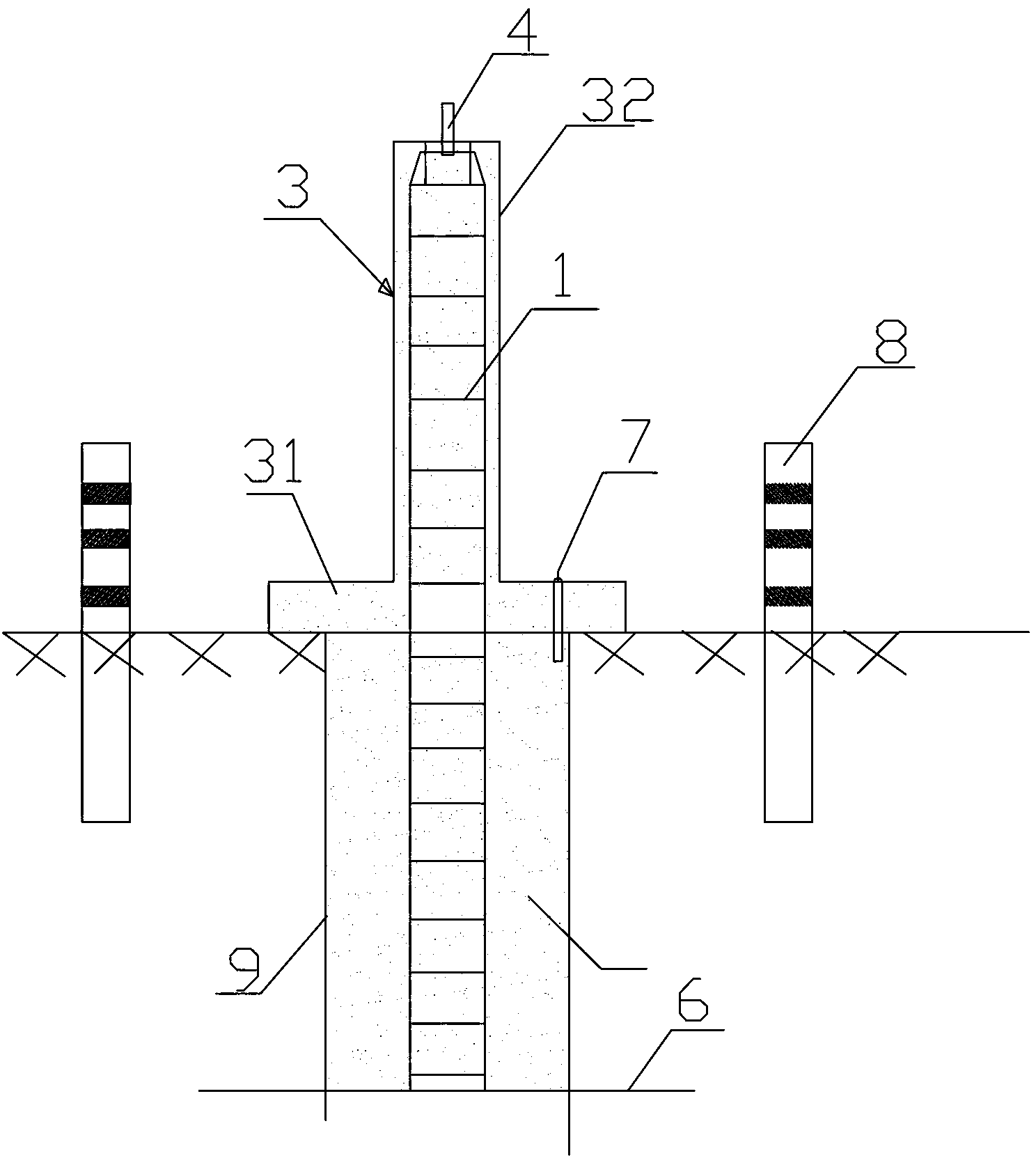
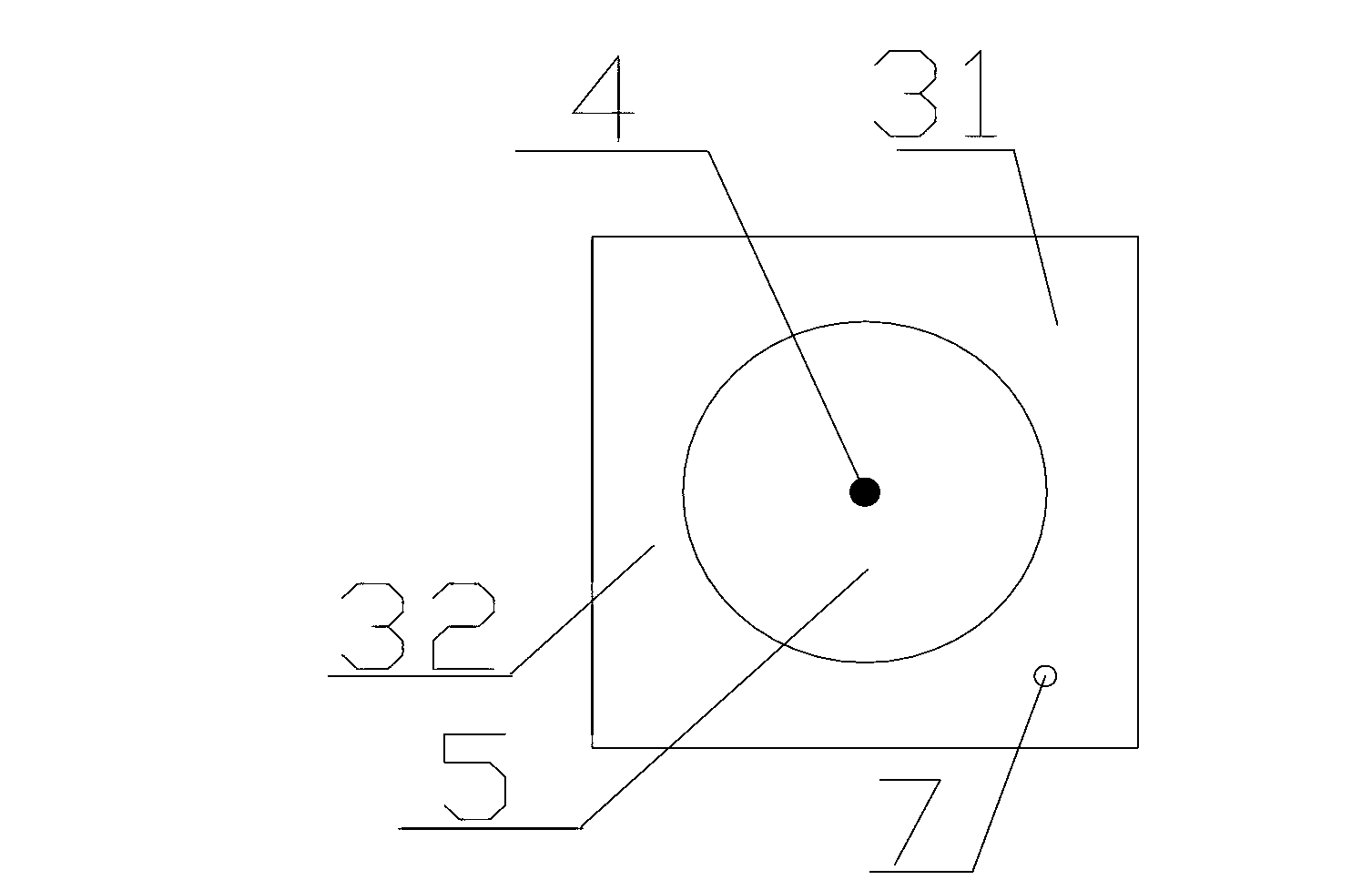
[0031] The manufacturing and embedding method of the forced centering observation pier used for precision engineering measurement of the present invention is as follows: figure 1 , figure 2 shown, including the following steps:

[0032] 1) Manually excavate the pile hole 9, and dig down to the bedrock 6; in the process of manually digging the pile hole 9, it is necessary to control the verticality of the pile hole 9, check the quality of the pile hole, clean up the virtual soil in the pile hole 9, and remove the pile hole 9 stagnant water.

[0033] 2) Hang the reinforcement cage 1 into the pile hole 9. The bottom of the reinforcement cage 1 should be placed on the bedrock 6, and a steel reinforcement cage 1 with a ...


PUM


Abstract

The invention discloses a fabrication method of a forced centering observation pillar for precision engineering measurement and the observation pillar. The fabrication method comprises the steps that a pile hole is dug manually and downward to a bed rock; a steel reinforcement cage is placed in the pile hole in a hanging manner; the bottom of the steel reinforcement cage is placed on the bed rock; the height-set steel reinforcement cage is reserved above the ground surface; an underground concrete pile is poured in the pile hole; after the underground concrete pile is solidified, a formwork is erected and an overground concrete column is poured on the steel reinforcement cage reserved above the ground surface; a forced centering bolt is embedded in the center of the top end of poured concrete; the diameter of the forced centering bolt is required to be matched with a bolt hole at the bottom of an instrument base; a forced centering disk is embedded at the top end of the concrete embedded with the forced centering bolt; and the forced centering bolt penetrates through the center of the forced centering disk. According to the fabrication method of the forced centering observation pillar for the precision engineering measurement and the observation pillar, the technology is simple; the fabrication and embedding method is simple; the pillar is easy to fabricate, and convenient to use, and is not damaged easily; an observation error can be reduced; the observation accuracy is reliable; and specified requirements of standards are met.

Description

technical field [0001] The invention relates to a forced centering observation pier for precision engineering measurement. In particular, it relates to a method for making a forced centering observation pier for precision engineering measurement and the observation pier. Background technique [0002] Various measurement marks in precision engineering measurement are control points for construction or installation measurement control network, reference points and observation points for deformation observation. For example, in the construction process of the precision engineering control network, the measurement accuracy of angle measurement and edge measurement can be guaranteed by using corresponding precision instruments and a reasonable control network layout. However, when observing, it is necessary to ensure that the center of the instrument and the control point are on the same vertical line. During the measurement process, the instrument is usually set up on a convent...

Claims


Application Information

Patent Timeline
Patent Type & Authority Applications(China)
IPC IPC(8): G01C15/04E02D5/34
Inventor 董玉启吴伟林陈才新牛永忠刘一帆熊浩李海明贾清水
Owner TIANJIN 20 CONSTR
Why Eureka
Try Eureka