
Constant error calibration method of fiber-optic gyroscope based on double-calculation program

An error calibration, fiber optic gyroscope technology, applied in measurement devices, instruments, etc., can solve the problems of large amount of calculation, many mathematical models, inaccurate estimation model of misalignment angle, etc., and achieve the effect of small amount of calculation

Inactive Publication Date: 2013-05-01
HARBIN ENG UNIV
View PDF5 Cites 15 Cited by
  • Summary
  • Abstract
  • Description
  • Claims
  • Application Information

AI Technical Summary

Problems solved by technology

This method not only establishes many mathematical models, but also has a large amount of calculation; "Study on the Optimal Calibration Method of Strapdown Inertial Navigation" written by Shang Jie et al. An on-site optimal calibration method based on virtual noise is proposed. Although the method is simple in structure and easy to implement, the virtual noise setting method is not mentioned in the article. Whether the same group of virtual noise is introduced into different inertial components is suitable to be considered; application number In the Chinese invention patent of 201010523436.0 "A Calibration Method for Constant Value Drift of Fiber Optic Gyroscope", aiming at the rotation modulation strapdown inertial navigation system, a single-axis rotation mechanism is used to transform the IMU attitude, and the deviation and misalignment of the inertial device are established. Based on the quadratic linear equations for angle estimation, the estimation method for solving the horizontal constant value drift of the gyroscope
This method can only estimate constant value drift, and if there are unknown error sources in the system, resulting in an inaccurate estimation model for inertial device deviation and misalignment angle, it will affect the estimation accuracy

Method used


Image

  • Constant error calibration method of fiber-optic gyroscope based on double-calculation program
  • Constant error calibration method of fiber-optic gyroscope based on double-calculation program
  • Constant error calibration method of fiber-optic gyroscope based on double-calculation program

Examples


Embodiment

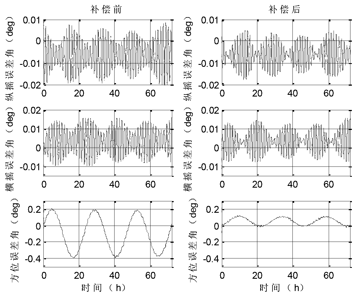
[0168] The beneficial effects of the present invention are verified as follows:

[0169] (1) Under the condition of Visual C++ simulation, the simulation experiment of this method is carried out:

[0170] The initial position of the carrier: 45.7796° north latitude, 126.6705° east longitude;

[0171] Equatorial radius: R=6378393.0m;

[0172] The gravitational acceleration on the earth's surface obtained by the universal gravitation: g=9.78049m / s 2 ;

[0173] Earth rotation angular velocity: Ω=7.2921158×10 -5 rad / s;

[0174] Constant: π=3.1415926535;

[0175] Fiber optic gyroscope constant drift: 0.005° / h;

[0176] Optical fiber gyroscope white noise error: 0.005° / h;

[0177] Optical fiber gyroscope scale factor error: 10ppm;

[0178] Accelerometer bias: 10 -4 g;

[0179] Accelerometer white noise error: 5×10 -5 g;

[0180] Accelerometer scale factor error: 10ppm;

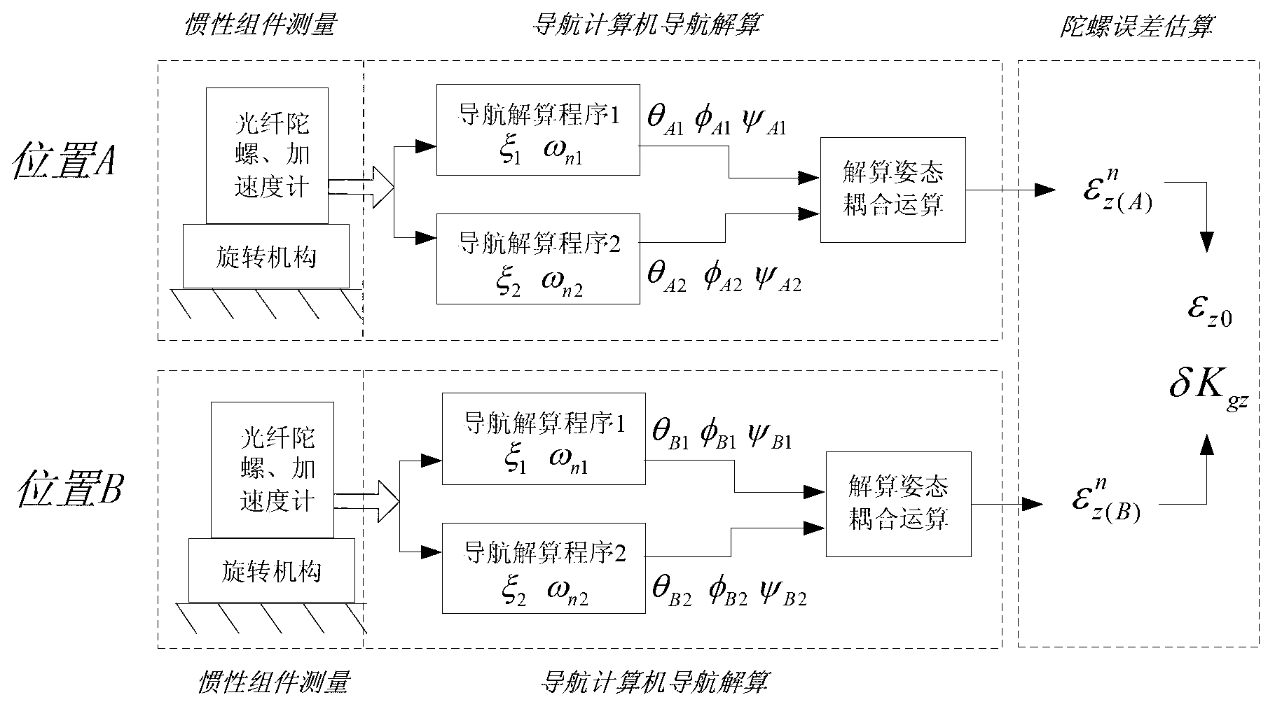
[0181] Navigation parameters: ξ 1 = 0.707, ω n1 =0.02, ξ 2 = 0.707, ω n2 = 0.002;

[0182] Samp...


PUM


Abstract

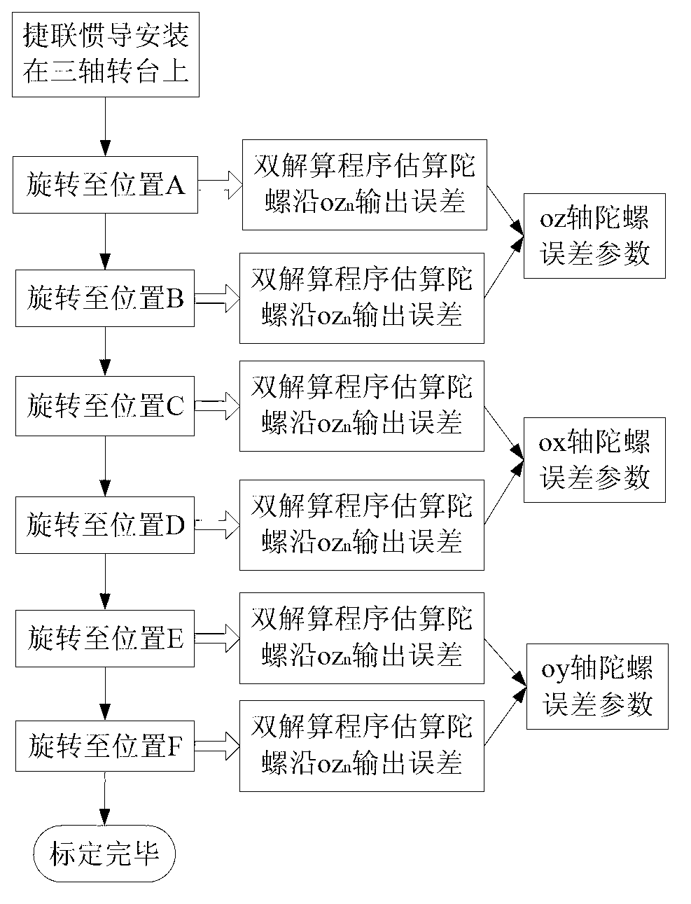
The invention discloses a constant error calibration method of a fiber-optic gyroscope based on a double-calculation program. The method utilizes a rotating mechanism to drive inertia components to rotate to six positions of each axis gyroscope in the forward direction and reversed direction of Z-axis of a navigation system respectively, wherein during the stay process of each position, measure values of a group of the inertia components are simultaneously served as input values of two groups of navigation calculation programs, and the navigation parameter setpoint values of the two groups of programs are different. Then the two groups of calculation posture information are further coupled and calculated, and constant drift and scale factor error of each axis gyroscope is estimated. The invention provides the scheme that measure values of one group of the inertia components are used as input in a navigation computer, the two groups of navigation program calculation are performed simultaneously, and the two groups of calculation results are utilized to further estimate the device error; no external criteria information is required, the calculation amount is small, and the operation is simple and easy; and the two groups of navigation calculation programs have same input information, no installation deviation and time delay exist, and output information has relativity.

Description

technical field [0001] The invention relates to the field of error testing of an inertial component of a strapdown inertial navigation system, in particular to a method for determining a constant value error of an optical fiber gyroscope based on a double solving program. Background technique [0002] The strapdown inertial navigation system SINS is a fully autonomous navigation system that does not require any external information and can continuously output carrier velocity, position, and attitude information, and is widely used in military and civilian fields such as aviation, aerospace, and navigation. It installs the inertial component (Inertial Measurement Unit, referred to as IMU, including gyroscope and accelerometer) directly on the carrier, uses the angular motion information of the carrier sensitive to the gyroscope to solve the conversion matrix from the carrier system to the navigation system, and then converts the acceleration The acceleration information measu...

Claims


Application Information

Patent Timeline
IPC IPC(8): G01C25/00
Inventor 孙枫王秋滢齐昭高伟高峰
Owner HARBIN ENG UNIV
Learn More