Method for measuring bunting position and energy based on energy distribution vector rate

An energy distribution and energy measurement technology, applied in the input/output process of data processing, sports accessories, instruments, etc., can solve the problems of low accuracy, inconvenient operation, and inability to directly sense the force of the touch, and reduce the total The effect of increased weight, area, and cost reduction

Active Publication Date: 2013-05-01
BEIJING TAIFANG TECH CO LTD
View PDF2 Cites 7 Cited by
  • Summary
  • Abstract
  • Description
  • Claims
  • Application Information

AI Technical Summary

Problems solved by technology

However, the capacitive touch screen cannot directly sense the strength of the touch, and can only sense the click of the skin, but cannot sense the click of fingernails, gloved fingers or other objects, so the operation is still inconvenient
At present, the above problems are mainly solved by the sensor group distributed under the touch screen, but it has several major disadvantages: 1. The sensor can only sense the force near it, so it is necessary to set up more sensors to form a group to cover the entire touch screen, so that It will increase the weight, complexity and power consumption of the device; 2. There are several layers of glass between the sensor and the finger touch. The energy of the finger touch can only be sensed by the sensor after being dispersed and attenuated by the glass, so the accuracy is not high. Difficult to accurately give the strength of the impact

Method used


Image

  • Method for measuring bunting position and energy based on energy distribution vector rate
  • Method for measuring bunting position and energy based on energy distribution vector rate
  • Method for measuring bunting position and energy based on energy distribution vector rate

Examples


Embodiment Construction

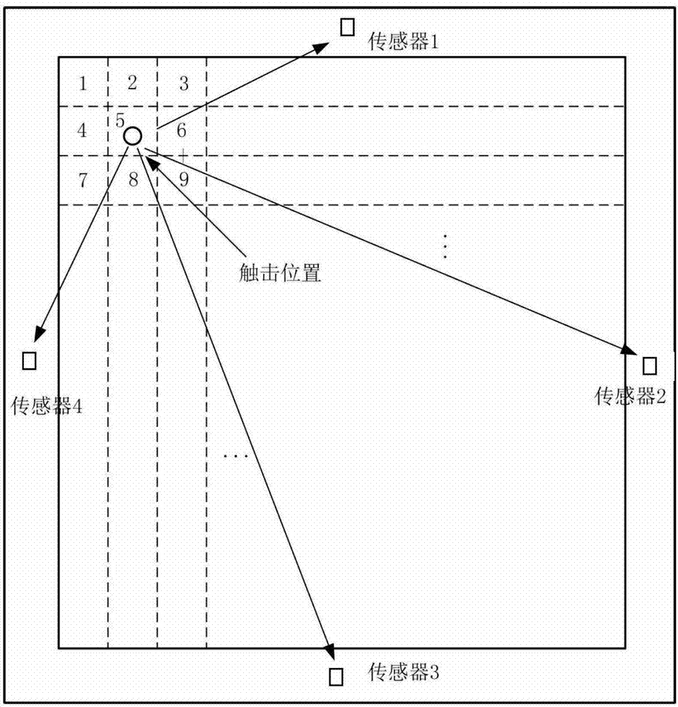
[0026] The touch device of the present invention needs to distribute more than two sensors under its sensing panel, divide the touch sensing area of ​​the sensing panel into several grids, and touch all the grids one by one with a given reference energy to obtain each Grid reference signal unit energy distribution vector; when a shock is sensed, the corresponding shock signal unit energy distribution vector is calculated according to the shock wave signal energy measured by the sensor, and it is compared with the reference signal unit energy distribution of each grid The vectors are compared one by one to determine the grid number where the strike is located, and calculate the corresponding strike energy to provide a basis for quantifying the strike.

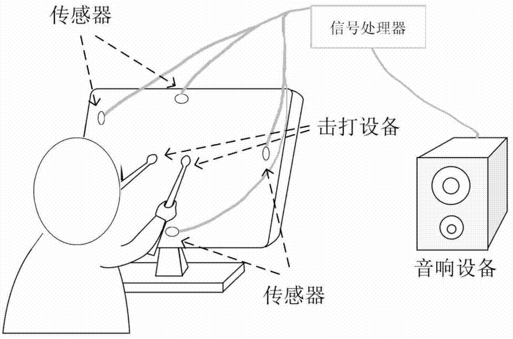
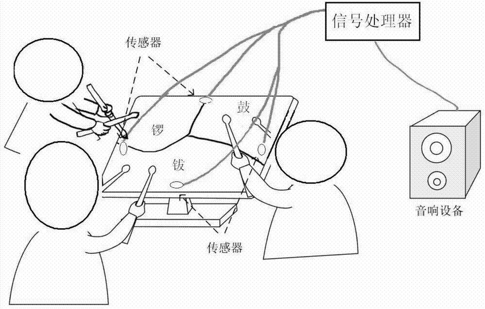
[0027] The present invention will be described in detail below by taking a touch control device with a touch screen as an example and referring to the accompanying drawings.

[0028] Such as figure 1 As shown, four sensors are ...


PUM


Abstract

The invention relates to a method for measuring a bunting position and energy based on an energy distribution vector rate. The method comprises the following steps: arranging more than two sensors in a dispersing form under a sensing panel of touch control equipment; dividing a bunting sensing area of the sensing panel into a plurality of grids; using the given standard energy for gradually bunting all the grids and obtaining a unit energy distribution vector of a standard signal of each grid; and when once bunting is sensed, calculating the unit energy distribution vector of a corresponding bunting signal according to impact wave signal energy sensed by the sensor, comparing the unit energy distribution vector of the corresponding bunting signal with the unit energy distribution vector of the standard signal of each grid in turn, thereby confirming the serial number of the bunting in the grid, and calculating the corresponding bunting energy. The invention changes a method for arranging a group sensor, such as an array sensor, and the like, for sensing the bunting force in the prior art; the method can be applied to the electronic equipment with the sensing panel, such as, a touch screen, a game control plate, a shooting target, and the like; and the method has a function of assisting or replacing the present positioning method based on the technologies, such as resistance, capacitance, and the like.

Description

technical field [0001] The invention relates to a method for measuring a touch position and a touch energy, in particular to a method for measuring a touch position and energy based on an energy distribution vector ratio for a touch device. Background technique [0002] Because of its simple and fast operation, touch devices have become the preferred configuration of current human-computer interaction electronic products. They can be seen everywhere from industry to home, from office to entertainment. While pursuing accuracy, stability, and convenience, people put forward more expectations and requirements, such as further enhancing sensitivity, reducing size, and reducing energy consumption. [0003] Taking electronic products with touch screens as an example, most mainstream technologies on the market currently use capacitive touch screens. However, the capacitive touch screen cannot directly sense the strength of the touch, and can only sense the click of the skin, but c...

Claims


Application Information

Patent Timeline
Patent Type & Authority Applications(China)
IPC IPC(8): G06F3/041A63F13/04
CPCG06F3/0414G06F3/0416G06F3/048G06F3/04142G06F3/0412G06F2203/04101G06F2203/04104G06F2203/04105
Inventor 杜朝亮姜丽丽卿新林
Owner BEIJING TAIFANG TECH CO LTD
Why Eureka
Try Eureka