Thoracic diagnosis assistance system and program

A diagnostic aid, chest technology, used in computer-aided medical procedures, diagnosis, diagnostic recording/measurement, etc., to solve problems such as difficult to grasp symptoms

Active Publication Date: 2013-05-01
KONICA MINOLTA MEDICAL & GRAPHICS INC
View PDF8 Cites 9 Cited by
  • Summary
  • Abstract
  • Description
  • Claims
  • Application Information

AI Technical Summary

Problems solved by technology

[0005] However, if only the maximum value (average value, median value, etc.)

Method used


Image

  • Thoracic diagnosis assistance system and program
  • Thoracic diagnosis assistance system and program
  • Thoracic diagnosis assistance system and program

Examples


no. 1 Embodiment approach 〉

[0039] Hereinafter, a first embodiment of the present invention will be described in detail with reference to the drawings. However, the scope of the invention is not limited to the illustrated examples.

[0040] [Configuration of Chest Diagnosis Support System 100]

[0041] First, the configuration will be described.

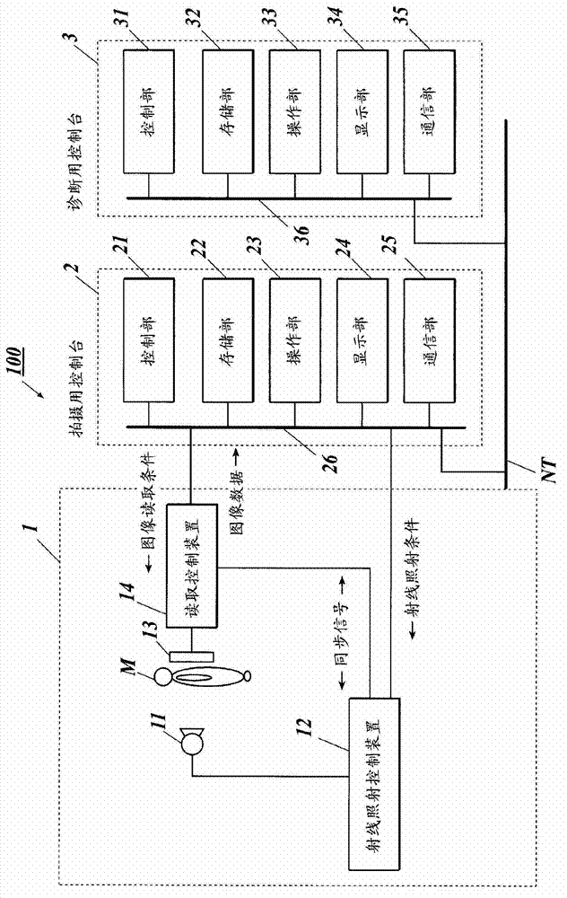
[0042] figure 1 The overall configuration of the chest diagnosis support system 100 in this embodiment is shown.

[0043] Such as figure 1 As shown, the chest diagnosis support system 100 is configured such that the imaging device 1 and the imaging console (console) 2 are connected by a communication cable or the like, and the imaging console 2 and the diagnostic console 3 are connected via a LAN (Local Area Network: local area network). and other communication network NT connections. Each device constituting the chest diagnosis assistance system 100 complies with the DICOM (Digital Image and Communications in Medicine: Digital Image and Communications in ...

no. 2 Embodiment approach >

[0124] Hereinafter, a second embodiment of the present invention will be described in detail with reference to the drawings. However, the scope of the invention is not limited to the illustrated examples.

[0125] Here, conventionally, in radiographing of chest static images, for example, as described in Japanese Patent Application Laid-Open No. 10-98587 (Known Document 1), a scattered ray removal grid (hereinafter referred to as a grid) for removing scattered rays is used. ) to shoot.

[0126] In addition, in recent years, as described in Japanese Unexamined Patent Application Publication No. 2005-312775 (public document 2), it has been proposed to use a radiation detector such as an FPD (flat panel detector) to perform dynamic imaging of the chest and apply it to However, in such a dynamic imaging system, imaging is performed using a grid as in still image imaging.

[0127] In known document 2, in order to reduce the subject's exposure dose in dynamic imaging in which the ...


PUM


Abstract

The invention is able to provide physicians with information that facilitates understanding of the clinical features of lung field ventilation and is effective for diagnosis. In particular, diagnostic information is provided with which appropriate diagnoses can be made even by physicians with little practical experience in using stethoscopes. With the diagnostic console (3) of this thoracic diagnosis assistance system (100), the control unit (31) extracts lung field regions from each of the multiple image frames obtained by imaging the movements of the chest, divides the extracted lung field regions into a plurality of sub-regions, and correlates the various sub-regions between the multiple image frames. Thereafter, the multiple image frames corresponding to each sub-region are analyzed, characteristic inspiratory values and characteristic expiratory values are calculated for each sub-region, ratios of the calculated characteristic inspiratory values to characteristic expiratory values are calculated and histograms of the ratios thus calculated are generated. The generated histograms are displayed on the display unit (34).

Description

technical field [0001] The present invention relates to a chest diagnosis support system and a program. Background technique [0002] In contrast to conventional radiographic imaging and diagnostics of still images of breasts using films / screens and luminescent phosphor panels, semiconductor image sensors such as FPDs (flat panel detectors) are used to capture dynamic images of breasts and apply them to diagnostics. try. Specifically, by utilizing the rapidity of the responsiveness of reading and erasing the image data of the semiconductor image sensor, and matching the timing of the reading and erasing of the semiconductor image sensor, pulsed radiation is continuously irradiated from the radiation source, within 1 second. Zhong took multiple shots to capture the dynamics of the chest. By sequentially displaying a series of a plurality of images obtained by imaging, a doctor can observe a series of movements of the chest accompanied by breathing movement, beating of the h...

Claims


Application Information

Patent Timeline
Patent Type & Authority Applications(China)
IPC IPC(8): A61B6/00
CPCA61B6/463G06T2207/10016G06T2207/10116G06T7/0016A61B6/563A61B6/5235A61B5/08A61B6/5217A61B6/4233G06T2200/24G06T2207/30061G06T2207/20021A61B6/50A61B5/113G16H50/30A61B5/0205A61B6/4035
Inventor 野地翔岛田哲雄村冈慎太郎长束澄也
Owner KONICA MINOLTA MEDICAL & GRAPHICS INC
Why Eureka
Try Eureka