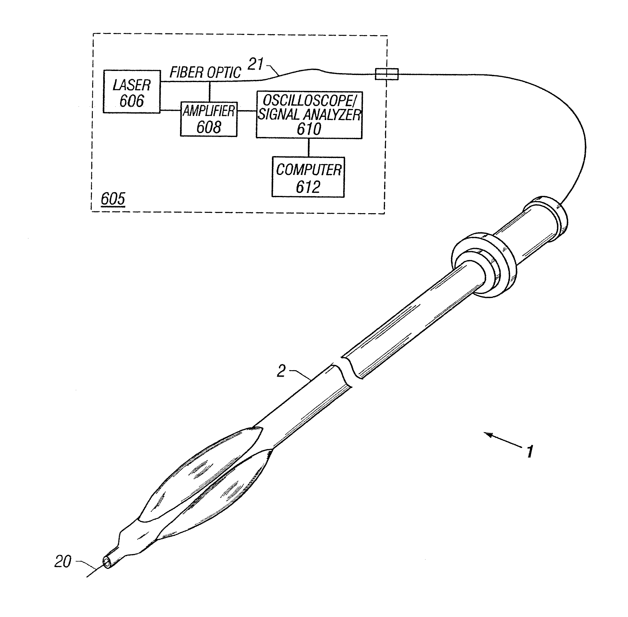
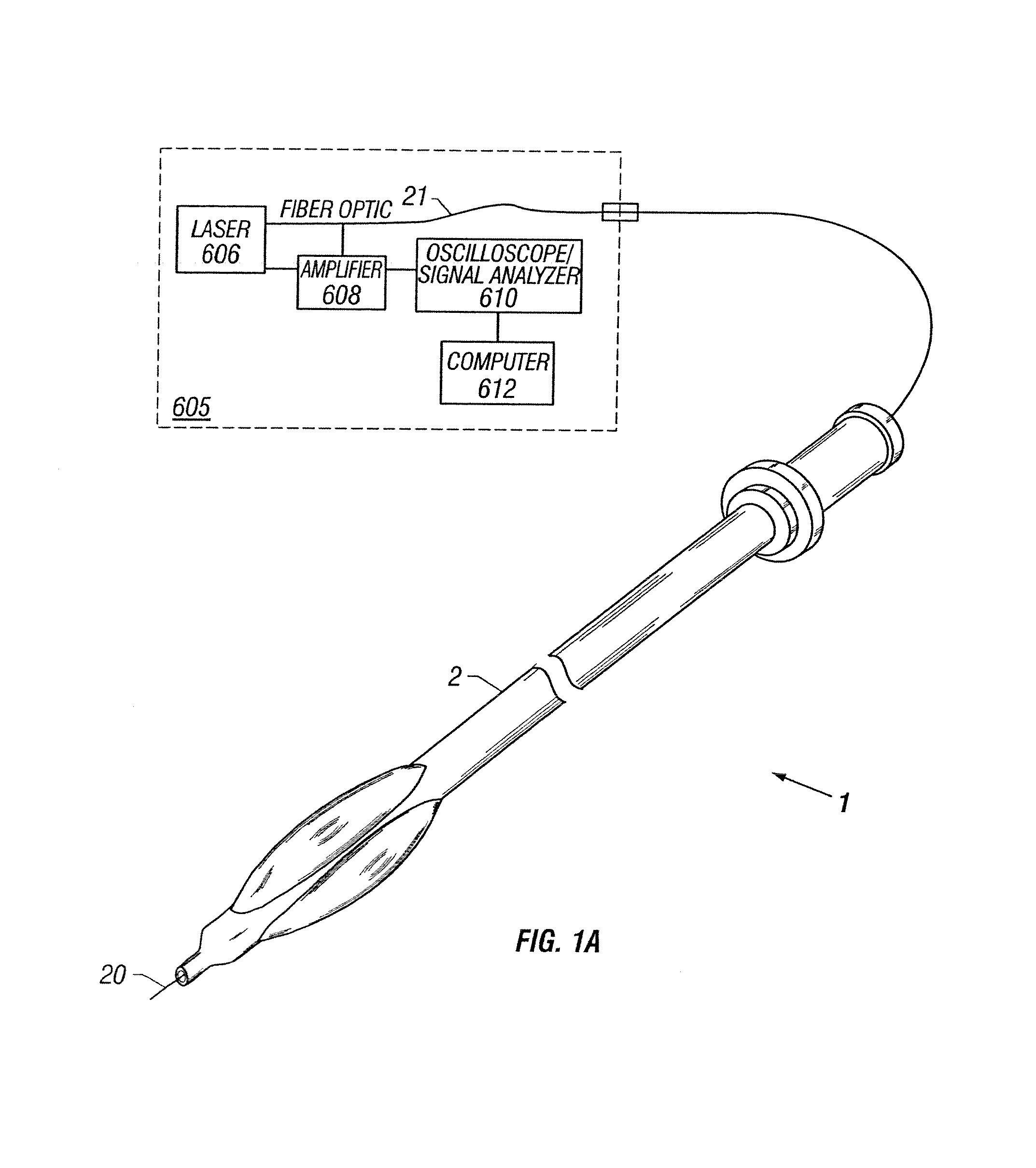
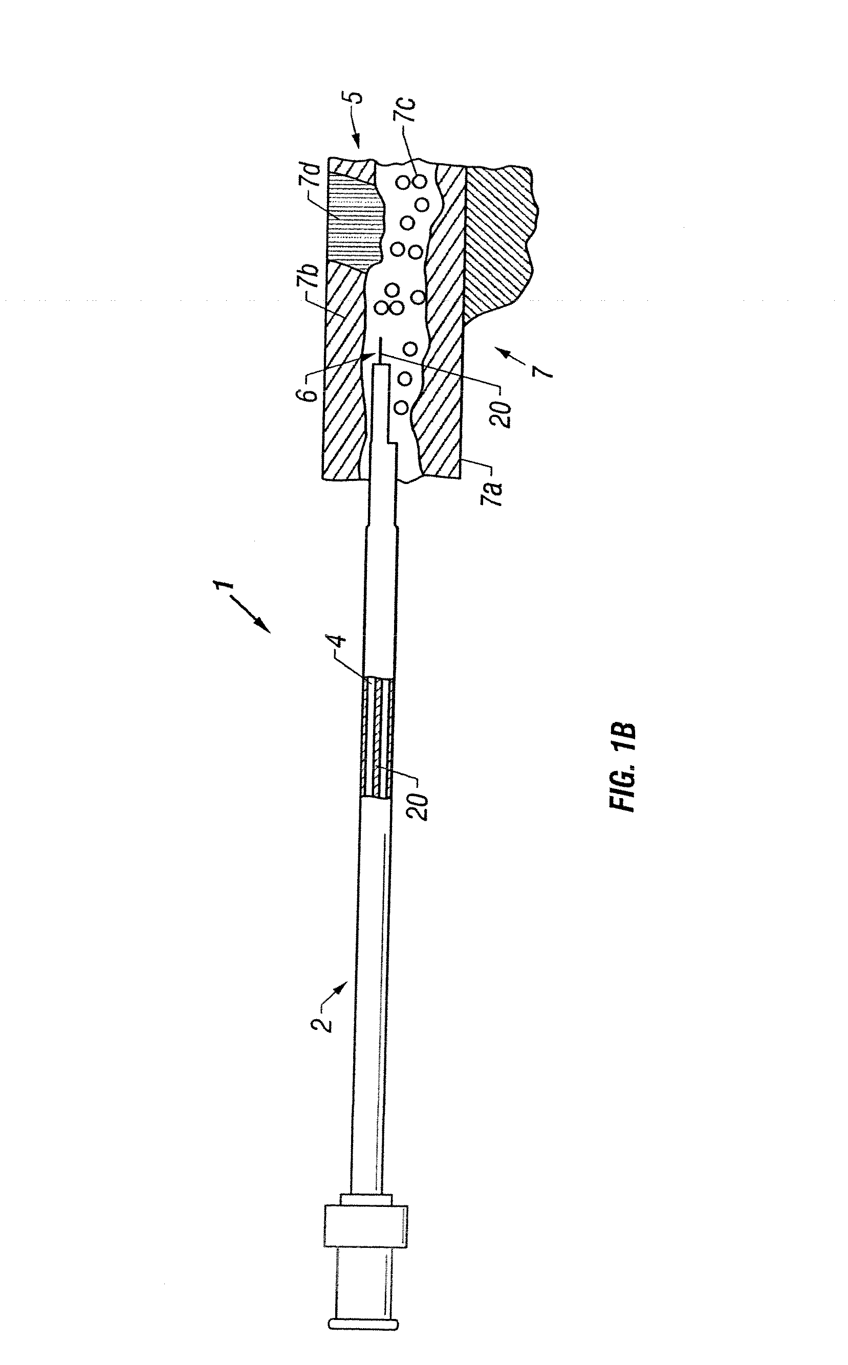
Catheter with optical fiber sensor

a catheter and optical fiber technology, applied in the field of catheters with optical fiber sensors, can solve the problems of increasing the risk of heart attack or stroke, the vast majority of these therapeutic devices are being used with very little information about in vivo, and the “lesion specific” treatment, as well as preventive measures, cannot be adequately envisioned or planned

Inactive Publication Date: 2008-06-12
ABBOTT CARDIOVASCULAR
View PDF58 Cites 139 Cited by
  • Summary
  • Abstract
  • Description
  • Claims
  • Application Information

AI Technical Summary

Problems solved by technology

When deposits accumulate in localized regions of a vessel, blood flow can be occluded or restricted, increasing the risk of heart attack or stroke.
The vast majority of these therapeutic devices, however, are being used with very little information about the in vivo biological environment, including for example, the hemorheology, vascular biology or histology and histochemistry of the vasculature being treated.
Without such information available to the physician, “lesion specific” treatment, as well as preventive measures, cannot be adequately envisioned or planned.
Many of these diagnostic devices have limitations that require measurement of properties, e.g. pressure or flow rate, at locations far removed from the specific site of disease such that accurate diagnosis is already compromised by merely using the device.
The result is that therapeutic strategies are often unilaterally rendered without relevant information concerning the lesion, surrounding vasculature, or the biomechanical environment—information which, if available, could be appropriately used to improve both acute and chronic outcomes for the patient.

Method used


Image

  • Catheter with optical fiber sensor
  • Catheter with optical fiber sensor
  • Catheter with optical fiber sensor

Examples


second embodiment

[0068]With reference to FIGS. 10 and 12, in a second embodiment, the optical fiber 20 may be inserted into the sheath 58 through a small lumen 53a in a dual lumen extrusion. Lumen 53a may have an interior diameter in the range of approximately 0.005-0.01 in. In one embodiment, lumen 53a has an inner diameter of approximately 0.007 in.

[0069]The second lumen 53b of the sheath 58 would allow catheter to be advanced and / or retracted within sheath 58. Lumen 53b may have an interior diameter in the range of approximately 0.050-0.10 in. In one embodiment, lumen 53b has an inner diameter of approximately 0.060 in.

[0070]In one embodiment of the configuration presented in FIG. 12, the optical fiber 20 may be partially or completely coupled within the optical fiber lumen 53a. In another embodiment, the optical fiber 20 may be freely movable to advance and / or rotate within the lumen 53a. Similar to the above-described design, sheath 58 may be independently advanced over the catheter for optical...

first embodiment

[0075]With reference to FIG. 14, in a first embodiment, the optical fiber 20 is molded (and thus affixed or secured) onto the inner surface 451 of the balloon tubing distal section as the tubing expands to form balloon 450. The optical fiber 20 may also be molded (and thus secured) onto the outer surface 452 of the balloon tubing distal section during the balloon blowing process. Alternatively, the optical fiber(s) 20 may be bonded (or secured) to the inner or outer surfaces 451, 452 of balloon 450 following the balloon blowing process. As stated above, some portion or the entire remaining length of optical fiber filament 20 may be positioned within the catheter shaft 410, e.g., inner member 420 and / or outer member 430.

[0076]With reference to FIG. 15, in a second arrangement, the optical fiber 20 is positioned between two layers 450a, 450b of balloon tubing. During the balloon blowing process, the optical fiber 20 is molded (and thus affixed) onto at least one of the two layers 450a...


PUM


Abstract

An apparatus and method to perform therapeutic treatment and diagnosis of a patient's vasculature through the use of an intravascular device having an optical fiber disposed therein. In an embodiment, the apparatus includes an intravascular device to perform a therapeutic treatment and at least one optical fiber disposed through the intravascular device. The optical fiber is configured to provide diagnostic information before, during, and after the therapeutic treatment. In an embodiment, diagnostic information includes vessel and blood characteristics such as hemodynamic characteristics, hematological parameters related to blood and blood components, and thermal parameters of the vasculature.

Description

CROSS-REFERENCE TO RELATED APPLICATIONS[0001]This is a continuation of prior U.S. patent application Ser. No. 09 / 872,310, filed on May 31, 2001.FIELD OF THE INVENTION[0002]This invention relates to the field of medical diagnosis and treatment by means of an intravascular device. More specifically, the present invention relates to a treatment catheter incorporating an optical fiber capable of providing diagnostic information before, during, and after the procedure.DESCRIPTION OF RELATED ART[0003]Arteriosclerosis, or more specifically atherosclerosis, is a common human ailment arising from the deposition of fatty-like substances, referred to as atheroma or plaque, on the walls of peripheral and coronary blood vessels. When deposits accumulate in localized regions of a vessel, blood flow can be occluded or restricted, increasing the risk of heart attack or stroke.[0004]Numerous approaches for reducing and removing such vascular deposits have been proposed, including balloon angioplasty...

Claims


Application Information

Patent Timeline
Patent Type & Authority Applications(United States)
IPC IPC(8): A61B5/00A61M29/02
CPCA61B5/0084A61B5/0086A61B5/02007A61B2017/22001A61B5/1459A61B5/6853A61B5/02154
Inventor AINSWORTH, ROBERT D.KILPATRICK, DEBORAHLEE, JEONG S.HURLEY, BRIDGET A.ELLIS, JEFFREY T.
Owner ABBOTT CARDIOVASCULAR
Why Eureka
Try Eureka