Engine suspension device with transfer case

A technology for engine mounts and transfer cases, applied in the direction of power devices, control devices, jet propulsion devices, etc., can solve the problems of poor working stability of the whole machine, low rationalization of layout structure, and low safety, and achieve simple structure, Easy-to-use promotional, connected and reliable effects

Inactive Publication Date: 2013-05-08
玉柴桩工(常州)有限公司
View PDF0 Cites 6 Cited by
  • Summary
  • Abstract
  • Description
  • Claims
  • Application Information

AI Technical Summary

Problems solved by technology

[0003] In order to overcome the deficiencies of the existing transfer case fixing methods, such as low safety, low rationalization of layout structure and poor working stability of the whole machine, the present invention provides an engine mount with a transfer case

Method used


Image

  • Engine suspension device with transfer case
  • Engine suspension device with transfer case
  • Engine suspension device with transfer case

Examples


Embodiment Construction

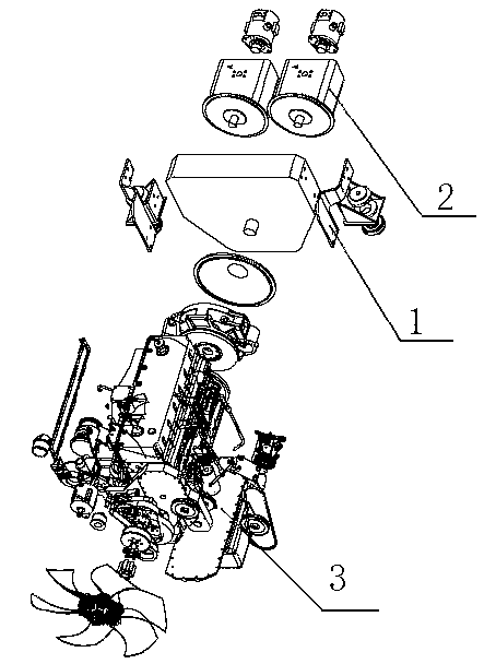
[0012] like figure 1 It is a structural schematic diagram of the present invention, an engine mount device with a transfer case, including a transfer case mount system 1, a hydraulic pump 2 and an engine 3, and one side of the transfer case mount system 1 is connected to the hydraulic pump 2 , the other side is connected with engine 3.

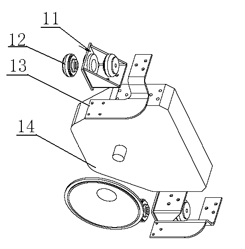
[0013] like figure 2 It is a schematic diagram of the structure of the transfer case mount of the present invention. The transfer case mount 1 is composed of a transfer case foot 11, a shock absorber 12, a side plate 13 and a transfer case 14. There are transfer case 14 on both sides. The case leg 11, the transfer case leg 11 is fixedly connected with the damping device 12, and the side plates 13 are fixed on both sides of the transfer case 14.

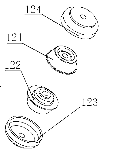
[0014] like image 3 It is a schematic diagram of the shock absorber of the present invention. The shock absorber 12 is composed of an upper rubber shock absorber 121, a lower rubber shock absorbe...


PUM


Abstract

The invention relates to the technical field of rotary drilling rigs, in particular to an engine suspension device with a transfer case. The device comprises a transfer case suspension system, a hydraulic pump and an engine, wherein the transfer case suspension system consists of transfer case supporting feet, shock-absorbing devices, side plates and the transfer case; one side of the transfer case is connected with the hydraulic pump, and the other side of the transfer case is connected with the engine; the transfer case supporting feet are arranged on the two sides of the transfer case and fixedly connected with the shock-absorbing devices; and one side of each side plate is fixed on each of the two side faces of the transfer case, and the other side of each side plate is fixed with a flywheel housing of the engine. The engine suspension device with the transfer case has a simple, compact and reasonable structure, is conveniently and quickly assembled and reliably connected and is easy to use and popularize, rear supporting feet of the engine are replaced, the work stability of the whole device is improved, and the work reliability of the rotary drilling rig is greatly improved.

Description

technical field [0001] The invention relates to the technical field of a rotary drilling rig, in particular to an engine suspension device with a transfer case. Background technique [0002] The transfer case is a mechanical product widely used in the power output of engines such as automobiles and construction machinery. Its function is to change the single output shaft of the engine into multiple output shafts, so as to facilitate more additional external devices. However, its fixation is mainly based on the connection with the engine flywheel shell end, and there is no independent fixing method and suspension system. If the transfer case is large or heavy, it is far from enough to fix the end face of the engine flywheel housing, which will easily make the engine top-heavy and cause the engine to roll over under vibration. Contents of the invention [0003] In order to overcome the deficiencies of the existing transfer case fixing methods, such as low safety, low ratio...

Claims


Application Information

Patent Timeline
Patent Type & Authority Applications(China)
IPC IPC(8): B60K17/344B60K5/12
Inventor 茹宏何佳鑫赫澜涛鲍宏平
Owner 玉柴桩工(常州)有限公司
Why Eureka
Try Eureka