Assembly interlocking prestressing force shear wall system and construction method thereof

A shear wall and prestressing technology, which is applied in the field of assembled interlocking prestressed shear wall systems, can solve the problems of easy formation of cross cracks, reduced wall bearing capacity, and difficult repair work, so as to achieve less wall cracks and easier assembly The effect of high degree and short construction period

Active Publication Date: 2013-05-08
HUNAN YUBAN CONSTR GRP CO LTD
View PDF11 Cites 3 Cited by
  • Summary
  • Abstract
  • Description
  • Claims
  • Application Information

AI Technical Summary

Problems solved by technology

[0002] At present, the shear walls, beams, and columns in construction projects are mostly cast-in-place. The cast-in-place shear walls are rigidly connected to the foundation and beams. On the one hand, the walls, foundation beams, and frame beams are limited. On the other hand, the wall has great lateral stiffness. Under the repeated action of earthquake load, the bending moment and shear force in the wall make it easy to form cross cracks, resulting in cracking of the shear wall and making the wall The bearing capacity of the body is reduced, and it is even destroyed in a major earthquake. Even if the damaged shear wall remains after the earthquake, its repair work is very difficult and uneconomical
In addition, cast-in-place shear walls require a large amount of formwork, and the construction speed is also greatly limited

Method used


Image

  • Assembly interlocking prestressing force shear wall system and construction method thereof
  • Assembly interlocking prestressing force shear wall system and construction method thereof
  • Assembly interlocking prestressing force shear wall system and construction method thereof

Examples


Embodiment 1

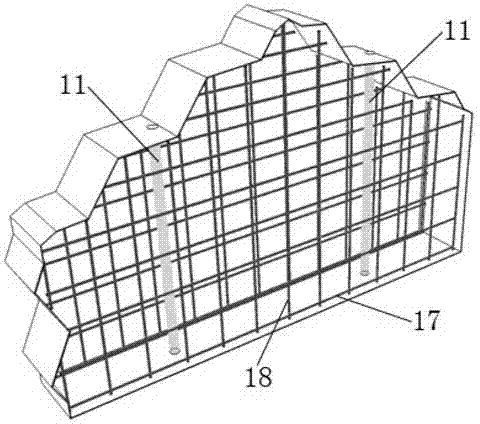
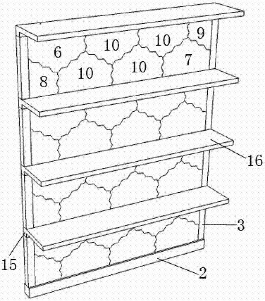
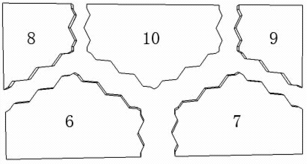
[0041] See attached figure 1 , attached Image 6 And attached Figure 9 , an assembled interlocking prestressed shear wall system, including prestressed tendons 1, cast-in-place foundation beams 2, sights 4, composite wall panels 5, cast-in-place columns 3, cast-in-place beams 15, and cast-in-place floor slabs 16. The cast-in-place foundation beam 2 with through holes 12 forms a "concave" frame with the cast-in-place column 3, and the composite wall panel is embedded in it through the prestressed tendon 1, and the sight 4 is installed after the prestressed tendon 1 is stretched, and then poured The cast-in-place beams 15, cast-in-place floor slabs 16 and cast-in-place columns 3 of the first layer form a new "concave" frame, and then assemble the second layer of composite wall panels 5. The construction of other layers is the result of this process. repeat.

[0042](a) Preparatory work: including the prefabrication preparation work of various wall panels in the composite wal...


PUM


Abstract

The invention discloses an assembly interlocking prestressing force shear wall system which comprises prestressing tendons 1, a cast-in-place foundation beam 2, sighting telescopes 4, combination wallboards 5, cast-in-place columns 3, a cast-in-place beam 15 and a cast-in-place floor slab 16. A concave-shaped frame is formed by the cast-in-place foundation beam 2 with a through hole 12 reserved and the cast-in-place columns 3. The combination wallboards 5 are embedded into the concave-shaped frame through the prestressing tendons 1. The sighting telescopes 4 are installed after the prestressing tendons are stretched and pulled. Then, the cast-in-place beam 15 and the cast-in-place floor slab 16 on a first floor and the cast-in-place columns 3 on a second floor are poured. A new concave-shaped frame is formed. Then, the combination wallboard 5 on the second floor is assembled. Construction of other floors is repetition of the process. Provided is a construction method of the assembly interlocking prestressing force shear wall system. The construction method comprises the steps of (a) preparation work, (b) foundation excavation, (c) pouring of foundation, the cast-in-place foundation beam 2 and the cast-in-place columns 3 on the first floor, (d) assembly of the combination wallboard 5 on the first floor, (e) pouring of the cast-in-place beam 15 and the cast-in-place floor slab 16 on the first floor and the cast-in-place columns 3 on the second floor, (f) assembly of the combination wallboard 5 on the second floor, and (g) construction on other floors.

Description

technical field [0001] The present application relates to a shear wall, more precisely an assembled interlocking prestressed shear wall system. Background technique [0002] At present, the shear walls, beams, and columns in construction projects are mostly cast-in-place. The cast-in-place shear walls are rigidly connected to the foundation and beams. On the one hand, the walls, foundation beams, and frame beams are limited. On the other hand, the wall has great lateral stiffness. Under the repeated action of earthquake load, the bending moment and shear force in the wall make it easy to form cross cracks, resulting in cracking of the shear wall and making the wall The bearing capacity of the body is reduced, and it is even destroyed in a major earthquake. Even if the damaged shear wall survives after the earthquake, its repair work is very difficult and uneconomical. In addition, cast-in-place shear walls require a large amount of formwork, and the construction speed is al...

Claims


Application Information

Patent Timeline
IPC IPC(8): E04B2/64E04B1/98E04C2/30E04G21/00
Inventor 黄靓陈永亮王天凤许利文许仲远张怀安许颀江超
Owner HUNAN YUBAN CONSTR GRP CO LTD
Why Eureka
Try Eureka