Reference voltage generation circuit

A technology for generating circuits and reference voltages. It is applied in the direction of adjusting electrical variables, control/regulating systems, instruments, etc. It can solve the problem of small operating voltage range and achieve the effect of reducing power consumption.

Active Publication Date: 2013-05-08
SHANGHAI HUAHONG GRACE SEMICON MFG CORP
View PDF6 Cites 20 Cited by
  • Summary
  • Abstract
  • Description
  • Claims
  • Application Information

AI Technical Summary

Problems solved by technology

[0012] The technical solution of the present invention solves the problem that the working voltage range of the reference voltage generation circuit in the prior art is small

Method used


Image

  • Reference voltage generation circuit
  • Reference voltage generation circuit
  • Reference voltage generation circuit

Examples


Embodiment Construction

[0034] In order to make the above objects, features and advantages of the present invention more comprehensible, specific implementations of the present invention will be described in detail below in conjunction with the accompanying drawings.

[0035] In the following description, specific details are set forth in order to provide a thorough understanding of the present invention. However, the present invention can be implemented in many other ways than those described here, and those skilled in the art can make similar extensions without departing from the connotation of the present invention. Accordingly, the present invention is not limited to the specific embodiments disclosed below.

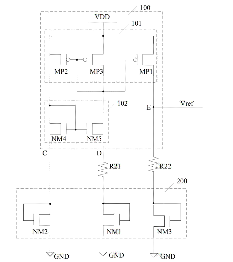
[0036] image 3 A schematic circuit diagram of the first embodiment of the reference voltage generating circuit of the present invention is shown. refer to image 3, the reference voltage generation circuit includes: a current mirror unit 100, a first resistor R21, a second resistor R22 ...


PUM


Abstract

Provided is a reference voltage generation circuit. The reference voltage generation circuit comprises a current mirror unit, a first resistance, a second resistance and a temperature coefficient compensation unit. The temperature coefficient compensation unit comprises a first N-channel metal oxide semiconductor (NMOS) tube, a second NMOS tube and a third NMOS tube. A grid electrode and a drain electrode of the first NMOS tube are connected with each other, and are connected with a second end of the first resistance, and a source electrode of the first NMOS tube is connected with the ground. A grid electrode and a drain electrode of the second NMOS tube are connected with each other, and are connected with a first node of the current mirror unit, and a source electrode of the second NMOS tube is connected with the ground. A grid electrode and a drain electrode of the third NMOS tube are connected with each other, and are connected with a second end of the second resistance, and a source electrode of the third NMOS tube is connected with the ground. The first NMOS tube, the second NMOS tube and the third NMOS tube work in a subthreshold region or a saturation region. A first end of the first resistance is connected with a second node of the current mirror unit. A first end of the second resistance is connected with a third node of the current mirror unit. A work voltage range of the reference voltage generation circuit is wide, and energy consumption of the reference voltage generation circuit is low.

Description

technical field [0001] The invention relates to the technical field of integrated circuits, in particular to a reference voltage generating circuit. Background technique [0002] In recent years, as portable electronic products occupy an increasing share in the market, the demand for reference voltage sources with low voltage and low power consumption has greatly increased. Reference voltage plays a vital role in electronic circuits or electronic systems. A stable reference voltage generally has two characteristics, one is high stability to temperature; the other is high resistance to power supply voltage changes. Because of its high stability, the bandgap reference voltage circuit is widely used in electronic systems such as analog / digital converters, digital / analog converters, and voltage rectifiers. [0003] figure 1 An existing reference voltage generation circuit is shown. refer to figure 1 , the reference voltage generating circuit includes: an error amplifier OPA,...

Claims


Application Information

Patent Timeline
Patent Type & Authority Applications(China)
IPC IPC(8): G05F3/26
Inventor 徐光磊
Owner SHANGHAI HUAHONG GRACE SEMICON MFG CORP
Why Eureka
Try Eureka