Two-stage wake-up circuit applicable to electronic toll collection system

An electronic toll collection system and wake-up circuit technology, applied in the direction of instruments, ticketing equipment, etc., can solve the problems of saving power consumption and failure to achieve, and achieve the effect of ensuring accuracy, reducing battery requirements, and extreme power consumption

Active Publication Date: 2013-05-08
INST OF ELECTRONICS CHINESE ACAD OF SCI
View PDF9 Cites 27 Cited by
  • Summary
  • Abstract
  • Description
  • Claims
  • Application Information

AI Technical Summary

Problems solved by technology

However, all the modules contained in this patent application work all the time

Method used


Image

  • Two-stage wake-up circuit applicable to electronic toll collection system
  • Two-stage wake-up circuit applicable to electronic toll collection system
  • Two-stage wake-up circuit applicable to electronic toll collection system

Examples


Embodiment Construction

[0061] The two-stage wake-up circuit of the ETC system of the present invention will be further described below in conjunction with the accompanying drawings.

[0062] 1. System structure

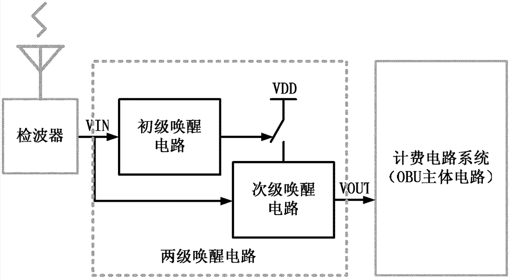
[0063] Figure 2a It is a simplified diagram of the system structure, and the whole system includes the primary wake-up circuit, the secondary wake-up circuit and the switch (excluding the front-end detector and the back-end billing circuit system). In the standby state, the primary wake-up circuit is in a working state, the secondary wake-up circuit is in a power-off dormant state, and its back-end circuit billing system is also in a dormant state. The primary wake-up circuit controls the power switch of the secondary wake-up circuit, and the secondary wake-up circuit controls whether the final wake-up signal is output, that is, controls the working / sleeping state of the back-end billing circuit system (OBU main circuit). The wake-up signal is received by the antenna and converted by the...


PUM


Abstract

The invention discloses a two-stage wake-up circuit applicable to an electronic toll collection (ETC) system, and relates to integrated circuit technique. The two-stage wake-up circuit applicable to the ETC system comprises a primary wake-up circuit and a secondary wake-up circuit. The primary wake-up circuit is low in power consumption and can work all the time under a standby state. The secondary wake-up circuit is moderate in sensitivity, good in stability, strong in process-voltage-temperature resisting ability, capable of accurately judging that whether an input signal is an ETC wake-up signal or not, but high in power consumption, the secondary wake-up circuit is in a dormant state under the standby state, and waking-up and dormancy of the secondary wake-up circuit are controlled by the primary wake-up circuit. According to the two-stage wake-up circuit, the primary wake-up circuit and the secondary wake-up circuit are combined to be used, so that the whole ETC two-stage wake-up circuit not only has the advantage of the primary wake-up circuit of being low in power consumption, but also has the advantages of the secondary wake-up circuit of being moderate in the sensitivity, good in the stability, low in mistake wake-up rate and the like. Meanwhile, a low-power-consumption wake signal amplifying circuit with no external polarization required is adopted in the primary wake-up circuit, and therefore power consumption of the primary wake-up circuit is lowered.

Description

technical field [0001] The invention relates to the technical field of integrated circuits, and is a two-stage wake-up circuit suitable for a national standard electronic toll collection (ETC) system. Background technique [0002] Intelligent wireless electronic toll collection system (Electronic Toll Collection, ETC) is a car toll station toll collection system that is gradually popularized and widely recommended by the country. This system installs an on-board wireless toll unit (On Board Unit, OBU) with the function of receiving and transmitting radio frequency signals at the corner of the car window, and sets a roadside unit (Roadside Unit, RSU) at the toll station. When the car passes through the toll booth, the roadside unit communicates with the on-board unit OBU through radio frequency signals, and automatically deducts the toll pre-charged in the OBU. Tolls can be realized during the driving process of the car, saving time and improving efficiency. The National In...

Claims


Application Information

Patent Timeline
IPC IPC(8): G07B15/06
Inventor 朱文锐杨海钢高同强刘飞程小燕张丹丹
Owner INST OF ELECTRONICS CHINESE ACAD OF SCI
Why Eureka
Try Eureka