This helps you quickly interpret patents by identifying the three key elements:
Problems solved by technology
Method used
Benefits of technology
Problems solved by technology
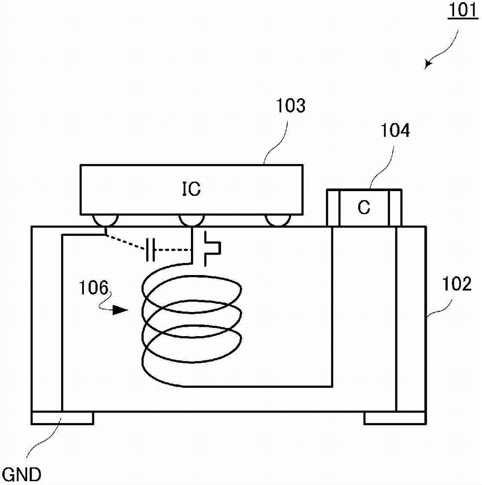
[0007] In the conventional DC-DC converter module, the wiring portion between the ground terminal connected to the ground potential of the substrate on which the module is mounted and the conversion IC mounted on the module also passes through the magnetic substrate, so the Impedance becomes high, and the potential of the ground port of the conversion IC tends to be higher than the actual ground potential
[0008] In addition, the wiring part between the winding and the conversion IC that flows the saw-like and pulse-like current is close to the ground port of the conversion IC, so there is coupling between the two to transmit noise, the potential of the ground port fluctuates greatly, and the noise level of the converter output very serious situation
Method used
Image
Click on the blue label to locate the original text in one second.
Reading with bidirectional positioning of images and text.
Examples
no. 1 Embodiment approach )
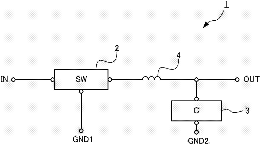
[0029] Figure 2A It is a circuit diagram of the DC-DC converter module 1 of the first embodiment.
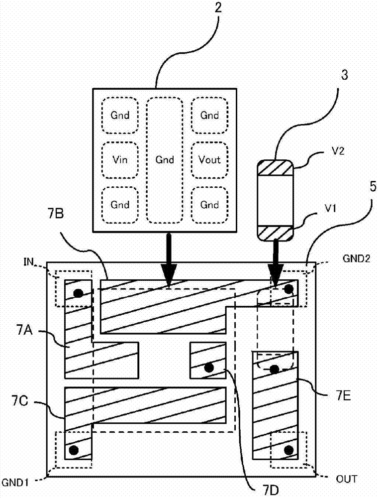
[0030] The DC-DC converter module 1 includes a conversion IC 2 , a capacitor 3 , and a winding 4 as circuit elements, and includes an input terminal IN, an output terminal OUT, and ground terminals GND1 and GND2 as external connection terminals.
[0031] The input electrode of the conversion IC 2 is connected to the input terminal IN, the ground electrode of the conversion IC 2 is connected to the ground terminal GND1, and the output electrode of the conversion IC 2 is connected to the output terminal OUT. And, the conversion IC 2 converts the voltage input to the input electrode, and outputs it from the output electrode.
[0032] The winding 4 is connected in series between the output electrode of the conversion IC 2 and the output terminal OUT. The first end of the capacitor 3 is connected between the winding 4 and the output terminal OUT, and the second end of the capacito...
no. 2 Embodiment approach )
[0045] Figure 3A It is a schematic sectional view of the DC-DC converter module 11 of the second embodiment. The DC-DC converter module 11 of the present embodiment differs from the first embodiment in that the shielding layer 16 is provided on the second surface side, which is the lower surface side of the formation layer of the winding 4 in the multilayer substrate 15 .
[0046] Figure 3B It is a graph explaining the improvement effect of the noise characteristic of the DC-DC converter module 11 based on a comparative test. In the comparison test, the relationship between the load current, the pulsating voltage and this embodiment was measured, and the above-mentioned Figure 2C Compare the relationship between the load current and the ripple voltage in the comparison configuration shown. In the figure, the horizontal axis represents the load current, and the vertical axis represents the ripple voltage. In addition, the solid line in a figure shows this embodiment, and...
no. 3 Embodiment approach )
[0049] Figure 4 It is a schematic sectional view of the DC-DC converter module 21 of the third embodiment. The DC-DC converter module 21 of this embodiment differs from the first embodiment in that a shield layer is omitted to form a multilayer substrate 25 . Such a configuration also suppresses the influence of the wiring impedance of the wiring portion 5A acting as a common impedance against noise, suppresses noise propagating through the wiring portion 5A, and improves the noise characteristics of the DC-DC converter module 21 .
PUM
Abstract
Provided is a DC-DC-convertor module having a favorable noise performance. A DC-DC convertor module (1) is provided with a multilayer substrate (5), a switching IC (2), and a coil (4). The multilayer substrate (5) has a structure in which component mounting electrodes are arranged on the upper surface, and an input terminal, an output terminal, and ground terminals (GND1, GND2) are arranged on the lower surface. The switching IC (2) is provided with an input electrode, an output electrode, and a ground electrode, is mounted on the upper surface of the substrate while each of the electrodes is connected to the component mounting electrodes, and switches the input voltages. The coil (4) is constituted to be helical in the multilayer substrate (5) around an axis in the substrate lamination direction. The coil (4) is connected at its lower surface side end to the input / output electrode of the switching IC (2).
Description
technical field [0001] The present invention relates to a DC-DC converter module and a multilayer substrate formed by arranging a DC-DC converter on a multilayer substrate and modularizing the module. Background technique [0002] Ultra-small regulator modules of the linear regulator type or switching regulator type are used in power supply circuits of portable devices and the like. A linear regulator type module converts all voltage fluctuation components into heat, so the voltage conversion efficiency is low, while a switching regulator type module has poor noise characteristics due to switching noise and the like. Therefore, it is expected that a DC-DC converter with high voltage conversion efficiency and excellent noise characteristics can be downsized and utilized in a power supply circuit of a portable device or the like. [0003] For the purpose of miniaturization of the DC-DC converter, the DC-DC converter is often formed on a multilayer substrate including a magnet...
Claims
Application Information
Patent Timeline
Application Date:The date an application was filed.
Publication Date:The date a patent or application was officially published.
First Publication Date:The earliest publication date of a patent with the same application number.
Issue Date:Publication date of the patent grant document.
PCT Entry Date:The Entry date of PCT National Phase.
Estimated Expiry Date:The statutory expiry date of a patent right according to the Patent Law, and it is the longest term of protection that the patent right can achieve without the termination of the patent right due to other reasons(Term extension factor has been taken into account ).
Invalid Date:Actual expiry date is based on effective date or publication date of legal transaction data of invalid patent.

