Double-shaft powder stirring humidifying device

A humidification device and powder technology, which is applied to mixers with rotating stirring devices, mixer accessories, transportation and packaging, etc., can solve problems such as low production efficiency, uneven humidification of powder mixing, and large driving resistance. Achieve the effects of easy maintenance, prevent powder accumulation and agglomeration, and reduce discharge resistance

Inactive Publication Date: 2013-05-22
HAIYUAN ENVIRONMENTAL SCI & TECH
View PDF2 Cites 4 Cited by
  • Summary
  • Abstract
  • Description
  • Claims
  • Application Information

AI Technical Summary

Problems solved by technology

The powder is usually forced to rotate at a speed of 30 to 80 rpm to the discharge port through the paddle group, which is prone to uneven mixing and humidification of the powder, large driving resistance, and low production efficiency

Method used


Image

  • Double-shaft powder stirring humidifying device
  • Double-shaft powder stirring humidifying device
  • Double-shaft powder stirring humidifying device

Examples


Embodiment Construction

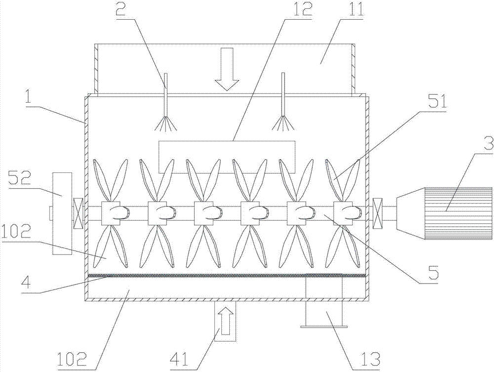
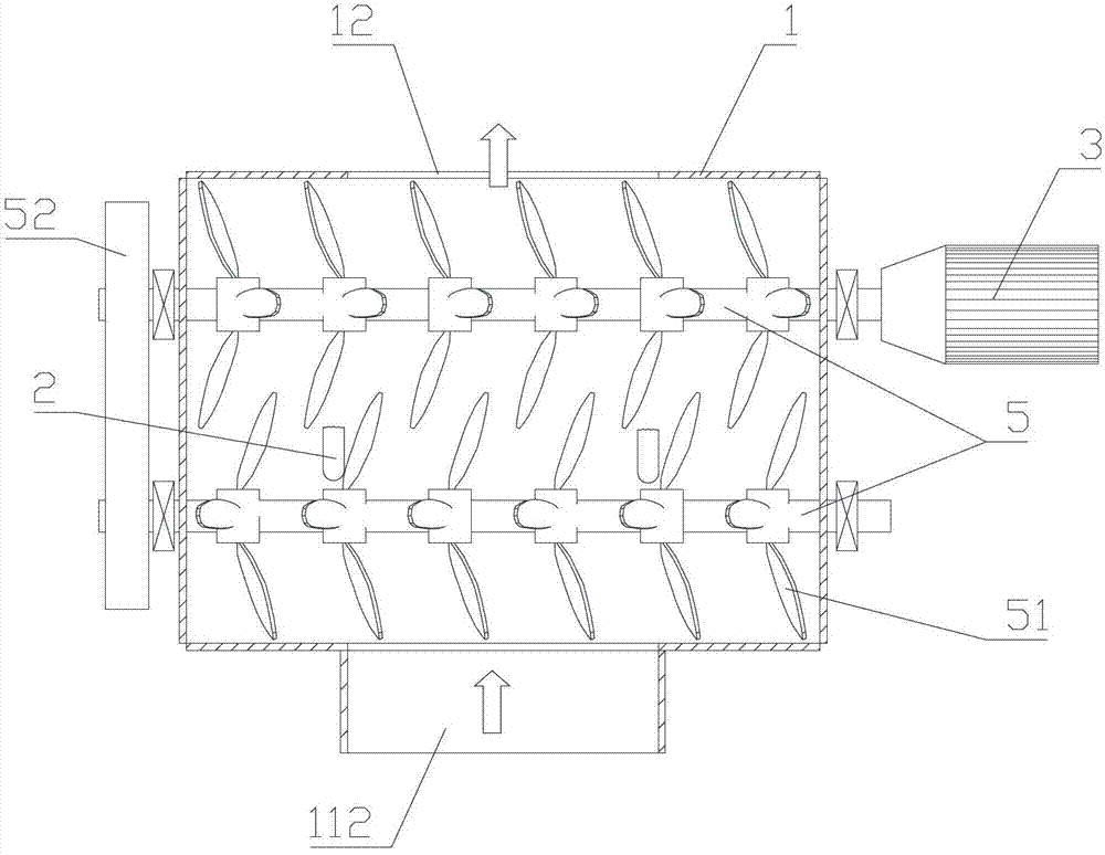
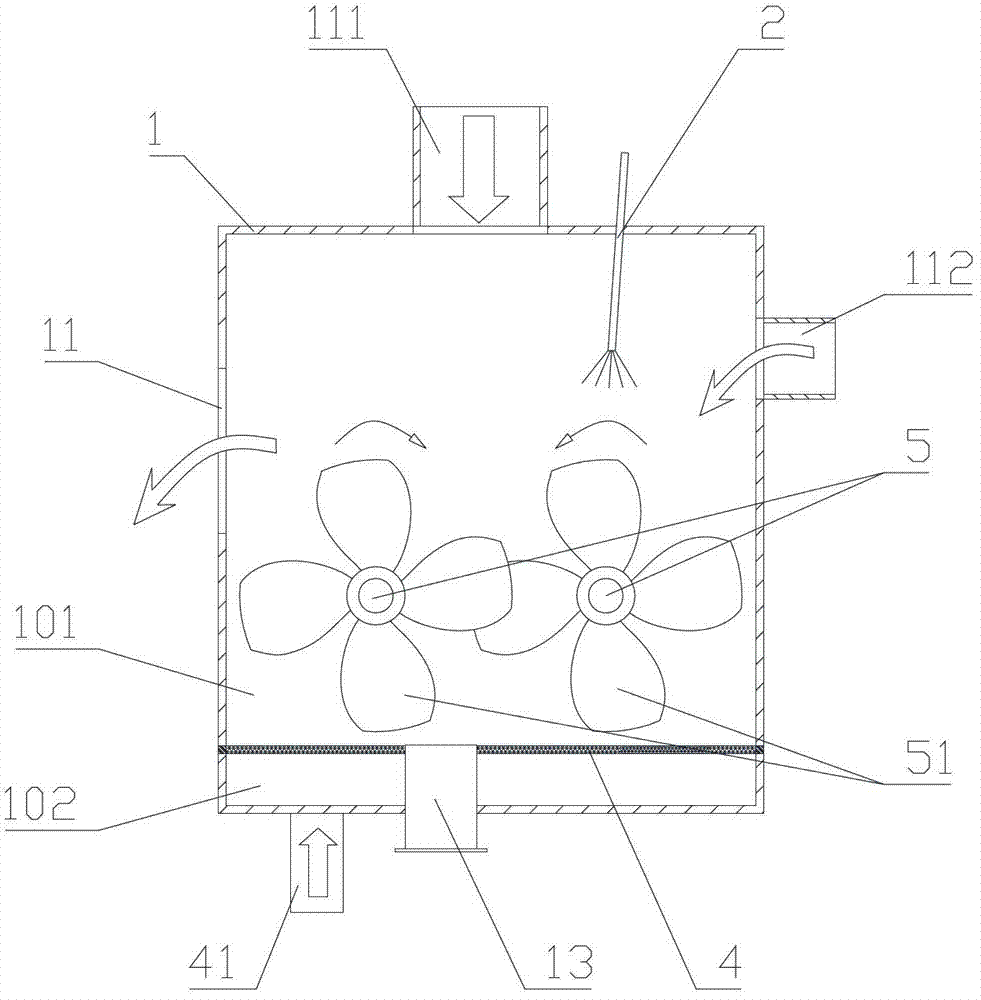
[0019] Such as Figures 1 to 3 Shown is an embodiment of the present invention, a double-shaft powder stirring and humidifying device, including a stirring bin 1, a stirring mechanism is arranged in the stirring bin, and a top wall or a side wall of the stirring bin is provided with A water spray device 2, the mixing chamber is provided with a feed inlet 11 and a discharge outlet 12, the stirring mechanism is driven by the driving device 3, the bottom of the stirring chamber is provided with a fluidization device, and the stirring mechanism is located at above the fluidization unit. The fluidization device includes a fluidization cloth 4, and the fluidization cloth is fixed on the side wall of the stirring bin to divide the inner space of the stirring bin into a stirring and humidifying area 101 above the fluidizing cloth and a flow area 101 below the fluidizing cloth. In the fluidization area 102, the bottom wall or the bottom of the side wall of the mixing chamber is provid...


PUM


Abstract

The invention discloses a double-shaft powder stirring humidifying device which is flue gas treatment equipment capable of evenly mixing and humidifying the powder to prepare various humidified powder mixtures. The device comprises a stirring bin, wherein a stirring mechanism is arranged in the stirring bin; a water spraying device is arranged at the upper part of the top wall or the side wall of the stirring bin; a powder inlet and a powder outlet are formed in the stirring bin; the stirring mechanism is driven by a driving device; a fluidifying device is arranged at the lower part of the stirring bin; and the stirring mechanism is arranged above the fluidifying device. The device disclosed by the invention is especially suitable for a half-dry flue gas treatment system.

Description

technical field [0001] The invention relates to flue gas treatment equipment, in particular to a biaxial powder stirring and humidifying device. Background technique [0002] At present, the twin-shaft mixer used to prepare highly active absorbents in flue gas treatment generally consists of two parts: a stirring mechanism and a driving device. The stirring mechanism includes two horizontal main shafts whose main body is located in the stirring mixing tank. A plurality of paddle groups arranged at intervals are fixed on the main shafts. There is a discharge port at the material end, and the power device drives the two main shafts to rotate in reverse. The powder is conveyed to the discharge port through the forced rotation of the paddle group at a speed of 30-80 rpm, which is prone to uneven mixing and humidification of the powder, large driving resistance, and low production efficiency. Contents of the invention [0003] The object to be achieved by the present inventio...

Claims


Application Information

Patent Timeline
Patent Type & Authority Applications(China)
IPC IPC(8): B01F7/06B01F15/02B01F3/12B01F27/71
Inventor 方培根汪伟李斌楼春晖葛介龙敖旭平傅正杰费月秋张龙涛
Owner HAIYUAN ENVIRONMENTAL SCI & TECH
Why Eureka
Try Eureka