Virtual pumping energy storage power station and energy storage generating method based on air compressing energy storage

A technology for compressed air energy storage and pumped storage power station, which is applied in the directions of hydroelectric power generation, hydroelectric power station, water conservancy project, etc., can solve the problems of limited application and promotion, large gas consumption, low efficiency, etc., to improve economic benefits and reduce economic efficiency. and efficiency loss, the effect of reducing construction costs

Active Publication Date: 2013-05-22
NORTH CHINA ELECTRIC POWER UNIV (BAODING)
View PDF5 Cites 20 Cited by
  • Summary
  • Abstract
  • Description
  • Claims
  • Application Information

AI Technical Summary

Problems solved by technology

The construction of a pumped storage power station has strict restrictions on geographical conditions, that is, it must have two large-capacity pools and a sufficiently high drop to be feasible and have a great impact on the surrou...

Method used


Image

  • Virtual pumping energy storage power station and energy storage generating method based on air compressing energy storage
  • Virtual pumping energy storage power station and energy storage generating method based on air compressing energy storage
  • Virtual pumping energy storage power station and energy storage generating method based on air compressing energy storage

Examples


Embodiment Construction

[0049] The present invention provides a virtual pumped storage power station based on compressed air energy storage and an energy storage power generation method. The present invention will be further described below in conjunction with the accompanying drawings and specific implementation methods.

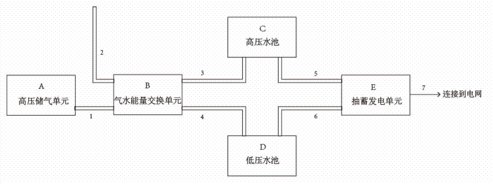
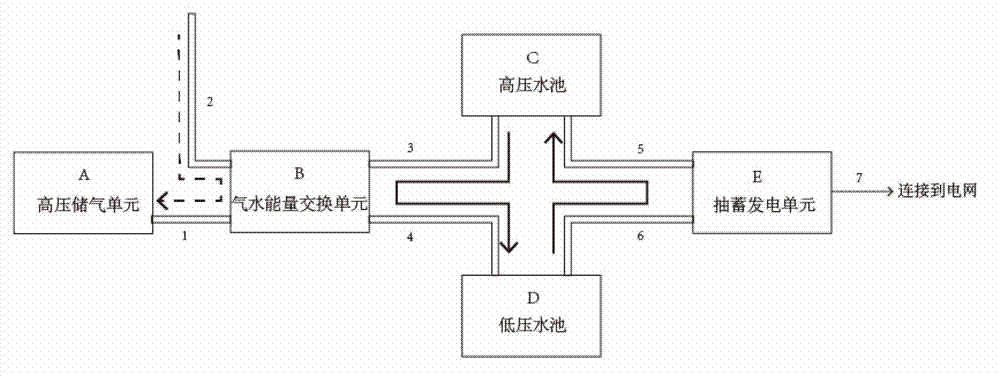
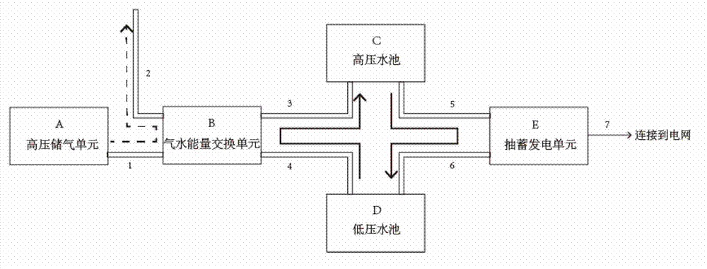
[0050] The overall structure of the virtual pumped storage power station is as follows: figure 1 As shown: the high-pressure gas storage unit A is connected to the gas-water energy exchange unit B through the high-pressure gas pipeline 1, the gas-water energy exchange unit B is connected to the low-pressure pool D through the first low-pressure water pipeline 4, and the low-pressure pool D is connected to the second low-pressure water pipeline 6 is connected to the pumped-storage power generation unit E; the low-pressure air pipeline 2 is connected to the air-water energy exchange unit B, and the air-water energy exchange unit B is connected to the high-pressure pool C through the ...


PUM


Abstract

The invention relates to the technology of large volume electric power energy storage, in particular to a virtual pumping energy storage power station and an energy storage generating method based on air compressing energy storage. A high pressure air storage unit is used as an energy storage element to be connected with an air water energy exchange unit. The air water energy exchange unit is respectively connected with a high pressure water pool and a low pressure water pool, wherein the high pressure water pool and the low pressure water pool are provided with stable pressure differences, and a pumping storing generating unit is respectively connected with the high pressure water pool and the low pressure water pool. When power is generated, the air water energy exchange unit utilizes expansion of high pressure gas to act to send water from the low pressure water pool to the high pressure water pool, and utilizes the water pressure difference of the two water pools to drive the pumping storage generating unit to generate power. When energy is stored, the pumping storage generating unit utilizes electric power of power grid to send water from the low pressure water pool to the high pressure water pool, the air water energy exchange unit utilizes the water pressure difference to act to compress air, the air is enabled to be highly-pressured and is sent into a high-pressure air storage unit. The virtual pumping energy storage power station and the energy storage generating method based on the air compressing energy storage adopt mature pumping an energy storage technology to achieve air compressing energy storage and control of power generating.

Description

technical field [0001] The invention relates to a large-capacity electric energy storage technology, in particular to a virtual pumped storage power station and an energy storage power generation method for mutual conversion between the potential energy of compressed gas and electric energy. Background technique [0002] Power generation output and load demand must always match in the power system. When there is no energy storage device, the conventional thermal power plant must be used as a backup and run under fire, which reduces the operating efficiency. Wind farms must also adjust their output by curtailing wind, wasting energy. [0003] Energy storage technology plays an important role in the four links of "generation-transmission-distribution-use" in the power grid operation process. After the energy storage link is introduced into the system, it can effectively realize the demand side management, eliminate the peak-valley difference between day and night, and smooth...

Claims


Application Information

Patent Timeline
IPC IPC(8): E02B9/00E02B9/06
CPCY02E10/22Y02E10/20
Inventor 姜彤毕经天陈伟丽马娴王静然
Owner NORTH CHINA ELECTRIC POWER UNIV (BAODING)
Why Eureka
Try Eureka