
Oil field underground liquid level detection method and device

A technology for liquid level detection and oil field wells, which is applied in construction and other fields, can solve the problems of increasing oil production costs, failing to measure reflected waves, and misjudgment of the state of oil barrels touching liquid, etc., to achieve improved oil recovery efficiency, easy implementation, and simple devices Effect

Inactive Publication Date: 2014-03-26
SUZHOU DAYI EQUIP TECH
View PDF4 Cites 0 Cited by
  • Summary
  • Abstract
  • Description
  • Claims
  • Application Information

AI Technical Summary

Problems solved by technology

However, there are some deficiencies in these two oil well liquid level measurement methods
For the first method, the problem is: on the one hand, the acoustic wave measurement method often has a large error or cannot measure the reflected wave due to the attenuation of the sound wave; Therefore, long-term real-time measurement cannot be achieved, and the cost of this measurement method is relatively high
For the second method, the problem is that only relying on the instantaneous decrease of the measured value of the steel wire rope gravity sensor to judge the state of the oil drum and obtain the height of the liquid level, its accuracy and reliability are low, and it is difficult to overcome the problem of the oil drum in the hundreds of meters. The influence of various disturbances in the process of moving up and down in the long oil well on the judgment of the liquid contact state is easy to misjudge the liquid contact state of the oil barrel, which is not conducive to the automatic control of the whole process of oil fishing
[0003] The length of the oil well is long, there are many internal disturbances, and the liquid level in the downhole changes in real time. The above two methods are likely to cause a mismatch between the pumping parameters of the pumping unit and the actual situation in the downhole, making the oil production process unreasonable and reducing the oil pumping of the oil well. Efficiency, increasing oil production cost

Method used


Image

  • Oil field underground liquid level detection method and device
  • Oil field underground liquid level detection method and device
  • Oil field underground liquid level detection method and device

Examples


Embodiment Construction

[0037] The method, device and working principle of the present invention are further described below with reference to design examples and accompanying drawings.

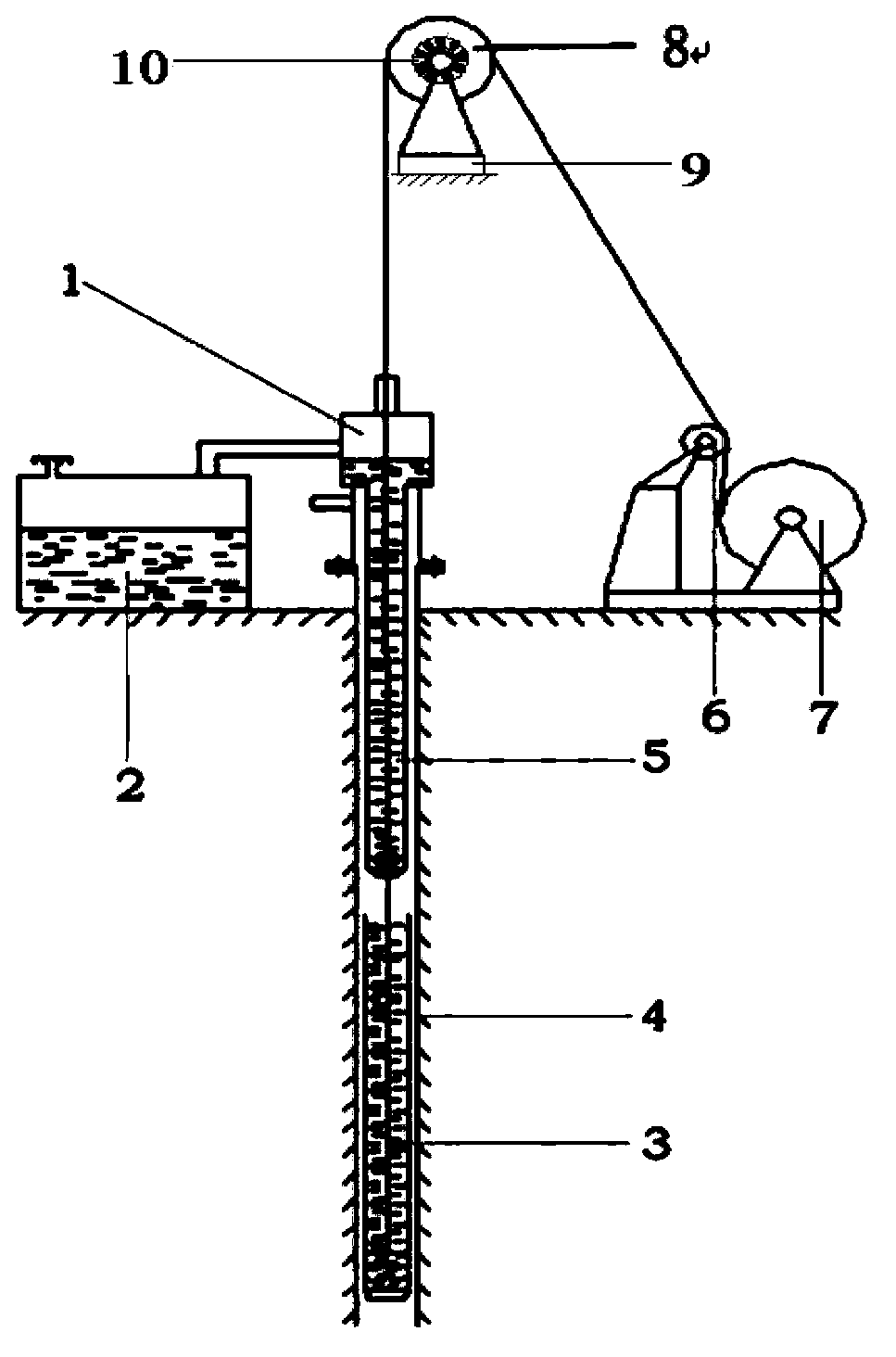
[0038] as attached figure 1 As shown, the process of oil production in the oil field is as follows: the lifting mechanism 7 and the rope discharger 6 control the retraction and release of the wire rope, the wire rope is directly connected to the oil fishing barrel 3 through the guide sheave 8, and the oil fishing barrel 3 is controlled to go up and down, and the oil passes through the fishing oil barrel. 3. The bottom one-way valve enters the oil drum, and the produced oil enters the oil guide pipe 5 through the one-way valve, and finally enters the oil storage tank 2 through the wellhead device 1.

[0039] The oilfield downhole liquid level detection method provided by the present invention specifically comprises the following steps:

[0040] The first step is to place the empty fishing oil barrel under the wellhe...


PUM


Abstract

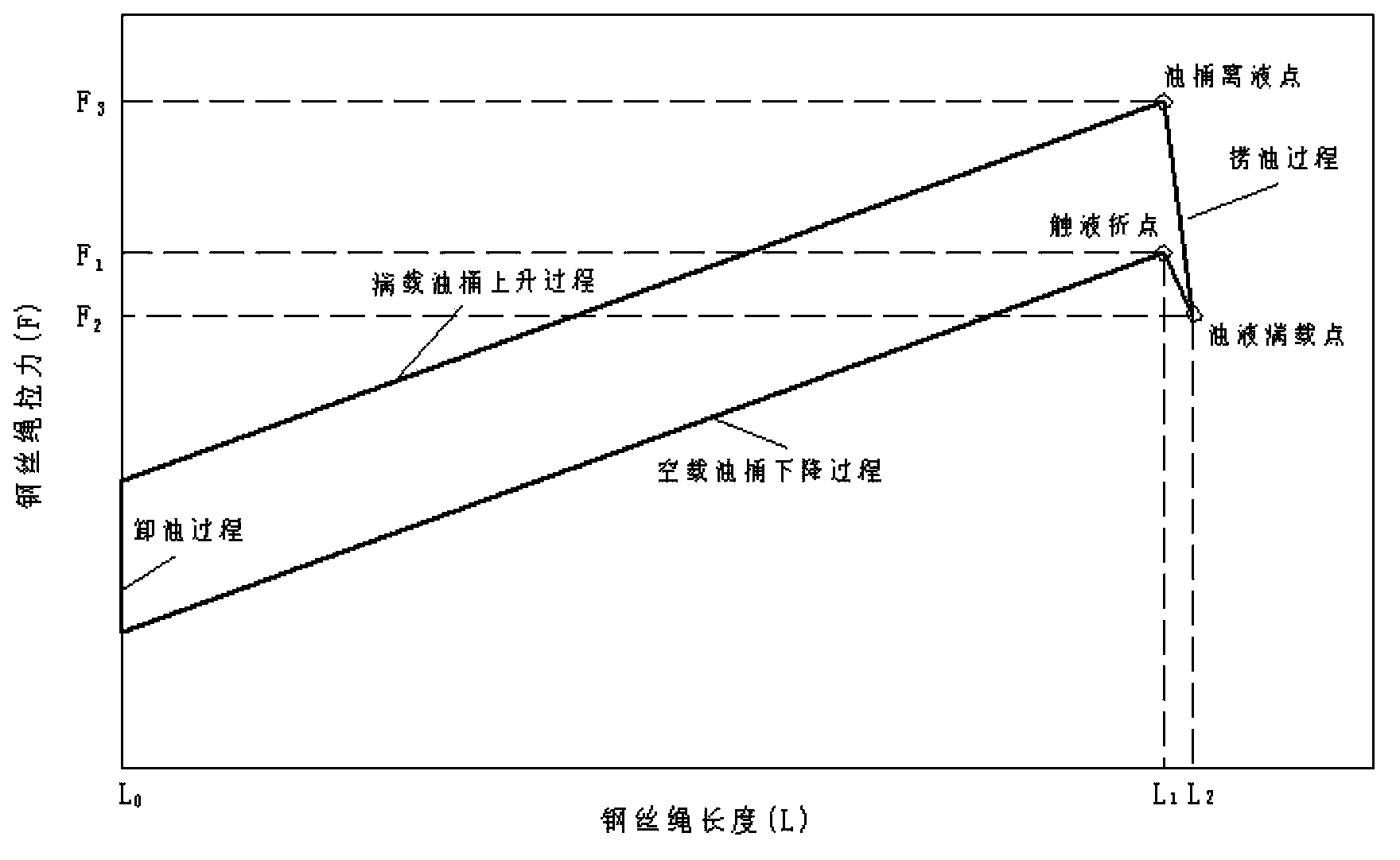
The invention discloses an oil field underground liquid level detection method and a device. The rope length is indirectly measured through an angular displacement sensor. The tension of a steel wire rope which is connected with an oil gaining barrel is measured through a force sensor. A turning point of a force signal change is detected by a signal processing module. An angular displacement signal and a steel wire rope tension signal of the rolling steel wire rope are measured by a measuring module and the angular displacement signal and the steel wire rope tension signal are collected in real time by the signal processing module. A noise signal is removed by filtering. A steel wire rope length-tension signal picture is obtained through the steel wire rope tension F and the steel wire rope dropping rope length L which is obtained by angular displacement calculation. A turning point of a curved line is detected in real time by taking advantage of a straight line partitioning algorithm on the rope length-tension signal picture. The corresponding underground rope length is the underground liquid level height. By means of the oil field underground liquid level detection method and the device, automatic tracking and real time effective measurement of the oil field underground liquid level can be achieved. The oil field underground liquid level detection method and the device are precise, reliable and easy to achieve. Oil extraction efficiency is improved and cost is reduced.

Description

technical field [0001] The invention relates to an oil production process monitoring technology, in particular to a method and a device for detecting a liquid level in an oil field downhole. Background technique [0002] At present, there are two main methods for oil level measurement: one is to generate sound waves with high-pressure gas or bullets at the wellhead, and use a sound wave receiver (usually a high-sensitivity microphone) installed at the wellhead to receive the reflected sound waves, which are received by the sound wave receiver. The sound wave is reflected and converted into an electrical signal, which is digitally processed by the control circuit to automatically calculate the depth of the liquid surface. Due to the effect of buoyancy, the value measured by the sensor decreases, and the oil level is judged by identifying this change. However, these two methods of oil well level measurement have some deficiencies. For the first method, the problem is: on the...

Claims


Application Information

Patent Timeline
Patent Type & Authority Patents(China)
IPC IPC(8): E21B47/047
Inventor 罗欣傅智春陈学东李小清严可涵周博
Owner SUZHOU DAYI EQUIP TECH
Learn More