Eureka AIR delivers breakthrough ideas for toughest innovation challenges, trusted by R&D personnel around the world.

Gas-assisted atomizing nozzle of atomization hyperviscous fluid

A gas-assisted, atomizing nozzle technology, applied in lighting and heating equipment, burners, etc., can solve the problems of atomization quality deterioration, poor economy, incomplete combustion, etc., to improve combustion efficiency and burnout degree, and meet operating requirements Environmental requirements, the effect of reducing the gas consumption of the factory

Active Publication Date: 2015-04-08
NO 11 INST OF NO 6 ACADEMY OF CHINA AEROSPACE SCI & TECH +1
View PDF6 Cites 0 Cited by
  • Summary
  • Abstract
  • Description
  • Claims
  • Application Information

AI Technical Summary

Problems solved by technology

[0002] In recent years, with the development of chemical deep processing, the quality of fuel oil that can be provided has been declining, and the viscosity has been greatly increased. The existing oil nozzles, whether it is mechanical atomization or gas-assisted atomization, have greatly deteriorated atomization quality, resulting in fire Combustion is unstable, burnout is low, output is insufficient, serious slagging, emission exceeds the standard, etc. It is necessary to improve the existing atomizer to meet the actual needs
[0003] For these high-viscosity fuel oils, they generally have the characteristics of high viscosity, difficulty in atomization, and the coke shell formed after pyrolysis slows down the evaporation of oil droplets. The following technical difficulties exist in their combustion: (1) The ignition time is long and the temperature rises Slow, start-up time is too long; (2) Incomplete combustion, black smoke, low combustion efficiency, poor economy: (3) High NOx emissions seriously pollute the environment

Method used


Image

  • Gas-assisted atomizing nozzle of atomization hyperviscous fluid
  • Gas-assisted atomizing nozzle of atomization hyperviscous fluid
  • Gas-assisted atomizing nozzle of atomization hyperviscous fluid

Examples


Embodiment Construction

[0027] The present invention will be described in further detail below in conjunction with the drawings and specific embodiments:

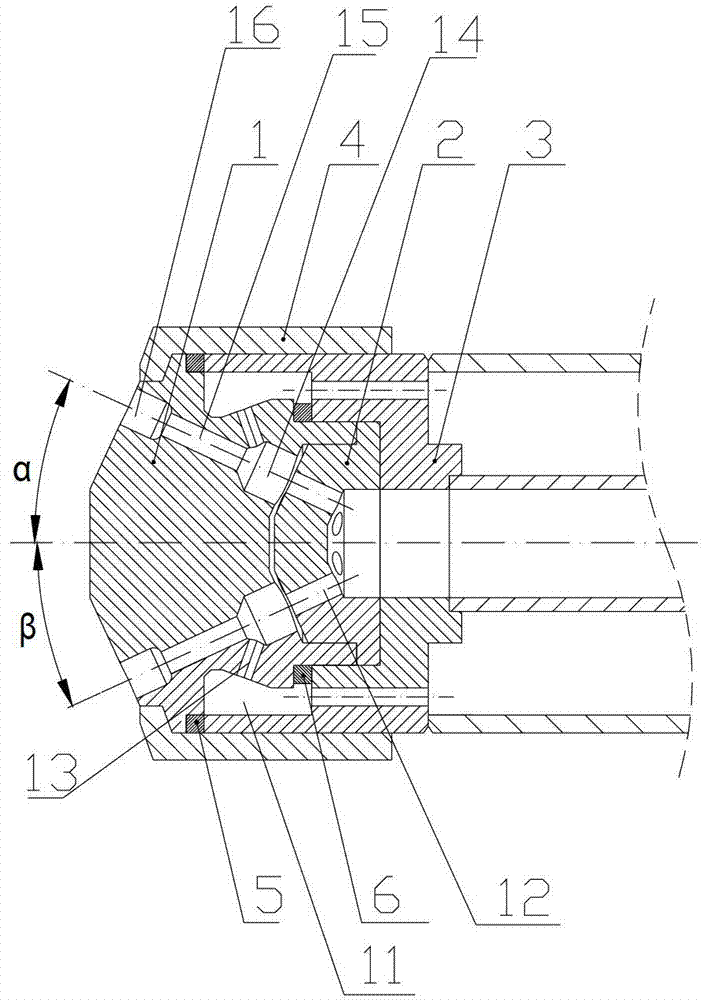
[0028] figure 1 It is a structural diagram of a gas-assisted atomization nozzle for atomizing high-viscosity fluids of the present invention. It includes a nozzle 1, a restrictor cone 2, a gas-liquid distributor 3, and a lock nut 4. The gas-liquid distributor includes a central atomization The gas pipeline and the high-viscosity liquid pipeline covering the periphery of the atomization gas pipeline; the lock nut seals and presses the nozzle on the outlet end of the gas-liquid distributor, and the nozzle presses the restrictor cone plate on the outlet end of the atomization gas pipe , The restrictor cone 2 is provided with a plurality of air holes 12, and the nozzle is provided with a plurality of mixing units with the same number as the air holes. The mixing unit includes a liquid hole 13, a premixing cavity 14, a mixing section 15 and a secondary mix...


PUM


Abstract

The invention relates to a gas-assisted atomizing nozzle of atomization hyperviscous fluid. The gas-assisted atomizing nozzle of the atomization hyperviscous fluid comprises a nozzle, a current-limiting cone plate,a gas-liquid distributor and a locking nut. The gas-liquid distributor comprises an atomizing gas pipeline and a hyperviscous fluid pipeline, wherein the atomizing gas pipeline is placed at the center and the hyperviscous fluid pipeline is coated on the atomizing gas pipeline. The locking nut tightly compresses on the outlet end of the gas-liquid distributer in a sealing mode and the nozzle tightly compresses the current-limiting cone plate on the outlet end of the atomizing gas pipeline. A plurality of air holes are formed in the current-limiting cone plate. The gas-assisted atomizing nozzle of the atomization hyperviscous fluid provides a gas assisted atomizing nozzle, strengthens mix between the gas and the liquid and effectively improves atomizing quality. When the gas-assisted atomizing nozzle of the atomization hyperviscous fluid is used for burning atomizing hyperviscous combustible liquid of a combustion device, ignition time can be greatly shortened, and when matched with a common air regulator, combustion efficiency and after-combustion degree of the combustible liquid are greatly improved.

Description

Technical field [0001] The invention relates to atomizing nozzles for liquid fuels used in combustion equipment of power station boilers, metallurgy, chemical industry and other industries, and atomization of other non-combustion equipment liquids, in particular to gas-assisted atomizing nozzles for atomizing heavy oil, residual oil and other related high-viscosity fluids It can meet the requirements of large flow and large turndown ratio. When used in combustion equipment, it can greatly reduce NOx emissions due to the use of off-combustion methods. Background technique [0002] In recent years, with the development of chemical deep processing, the quality of fuel oil that can be provided has been declining and the viscosity has greatly increased. The existing oil nozzles, whether they are mechanical atomization or gas-assisted atomization, have greatly deteriorated atomization quality, leading to fire Unstable combustion, low burnout, insufficient output, serious slagging, and ...

Claims


Application Information

Patent Timeline
Patent Type & Authority Patents(China)
IPC IPC(8): F23D11/38F23D11/40
Inventor 吕文豪张定海杨国华陈灿陈鹏飞谢佳池保华洪流
Owner NO 11 INST OF NO 6 ACADEMY OF CHINA AEROSPACE SCI & TECH
Why Eureka
Eureka Blog
Learn More