

Part control phase change air preheating system and air preheating method
A technology of air preheating and air preheater, which is applied in the field of boiler air preheating, can solve the coupling problems of low temperature corrosion and thermal efficiency, achieve the coupling problem of low temperature corrosion and thermal efficiency, improve the adjustment ability, improve safety and adaptive effect
- Summary
- Abstract
- Description
- Claims
- Application Information
AI Technical Summary
Problems solved by technology
Method used
Image

Examples
Embodiment 1
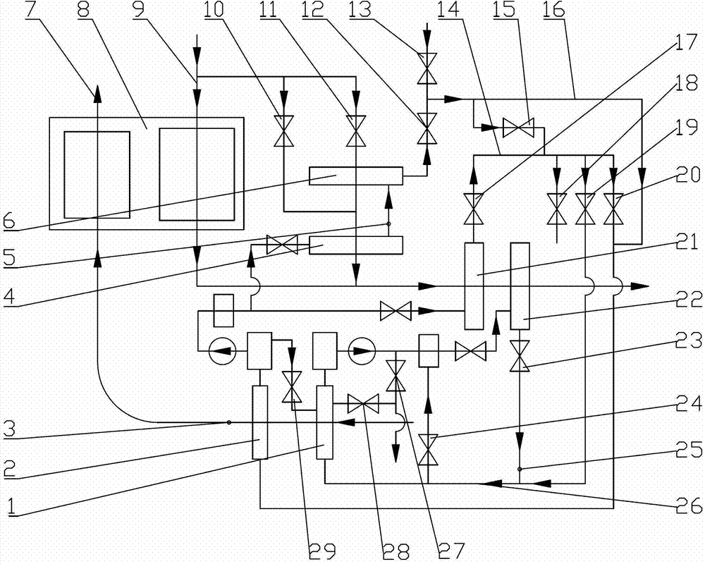
[0081] A sub-controlled phase change air preheating system, the system includes an air channel 7, a non-phase change air preheater 8 and a flue gas channel 9; the air in the air channel 7 and the flue gas in the flue gas channel 9 Heat exchange is performed in the non-phase-change air preheater 8; the system also includes a flue gas heat exchanger and an air heater; the flue gas heat exchanger is located after the non-phase-change air preheater 8 according to the flue gas flow direction on the flue gas passage 9; the air heater is located on the air passage 7 before the non-phase-change air preheater 8 according to the air flow direction; the steam outlet of the flue gas heat exchanger is supplied with steam through the flue gas heat exchanger The pipe is connected with the steam inlet of the air heater; the condensed water outlet of the air heater is connected with the water inlet of the flue gas heat exchanger through the condensed water pipe of the air heater. The steam sup...
Embodiment 2
[0086] A sub-controlled phase change air preheating system, the system includes an air channel 7, a non-phase change air preheater 8 and a flue gas channel 9; the air in the air channel 7 and the flue gas in the flue gas channel 9 Heat exchange is performed in the non-phase-change air preheater 8; the system also includes a flue gas heat exchanger and an air heater; the flue gas heat exchanger is located after the non-phase-change air preheater 8 according to the flue gas flow direction on the flue gas passage 9; the air heater is located on the air passage 7 before the non-phase-change air preheater 8 according to the air flow direction; the steam outlet of the flue gas heat exchanger is supplied with steam through the flue gas heat exchanger The pipe is connected with the steam inlet of the air heater; the condensed water outlet of the air heater is connected with the water inlet of the flue gas heat exchanger through the condensed water pipe of the air heater.
[0087] The ...
Embodiment 3
[0105] A sub-controlled phase change air preheating system, the system includes an air channel 7, a non-phase change air preheater 8 and a flue gas channel 9; the air in the air channel 7 and the flue gas in the flue gas channel 9 Heat exchange takes place in the non-phase change air preheater 8 . The system also includes a flue gas heat exchanger and an air heater; the flue gas heat exchanger is located on the flue gas channel 9 behind the non-phase-change air preheater 8 according to the flue gas flow; It flows to the air channel 7 before the non-phase-change air preheater 8 .
[0106] The flue gas heat exchanger is divided into high-temperature flue gas heat exchanger 21 and low-temperature flue gas heat exchanger 22 according to the flue gas flow direction; the air heater is divided into high-temperature air heater 2 and low-temperature air heating Device 1. The steam outlets of the high-temperature flue gas heat exchanger 21 and the low-temperature flue gas heat exchang...
PUM
 Abstract
Description
Claims
Application Information