A light source online detection device
A technology of detection device and measurement device, applied in the direction of measurement device, measurement of electricity, measurement of electric variables, etc., can solve the problems of light source winding problem, low control, influence of light and color measurement, etc., and achieves high test efficiency and convenient operation. , the effect of saving space
- Summary
- Abstract
- Description
- Claims
- Application Information
AI Technical Summary
Problems solved by technology
Method used
Image
Examples
Embodiment 1
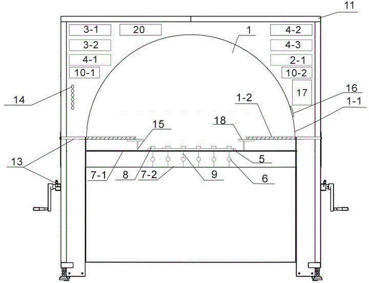
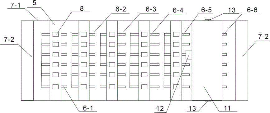
[0033] like figure 1 and figure 2 As shown, an online light source detection device includes an integrating sphere 1, a photometry device 2-1, a transmission mechanism 7 provided with a station plate 5, an electromagnetic interference generator 3, a power supply device 4, a switch control device, and a control unit 17 , driving mechanism 19, electrical measuring device 20 and cabinet 11, a row of 6 light source bases 8 in total, integrating sphere 1, photometric device 2-1, electrical measuring device 20, electromagnetic interference generator 3, The power supply device 4, the first switch control device 10-2, the control unit 17 and the driving mechanism 19 are all arranged in the cabinet 11, and an indicating device 14 is arranged on one side of the cabinet 11, and the indicating device 14 is electrically connected with the control unit 17, and the indicating device 14 It is a row of red and green indicator lights, the number of which is equal to the number of light source...
Embodiment 2
[0046] like Figure 4 As shown, different from Embodiment 1, this embodiment includes a driving mechanism 19, the driving mechanism 19 is connected with the hemispherical integrating sphere, a row of six light source bases 8 are arranged on the station plate 5, and the driving mechanism 19 drives the hemispherical integrating sphere Along the arrangement direction of the light source to be measured on the station board 5, it moves from left to right.
[0047] During actual measurement, all the light sources to be measured are turned on once controlled by the first switch control device 10-2, and the driving mechanism 19 drives the hemispherical integrating sphere to move, so that the light sources to be measured on the station board 5 are located at the measurement window 18 one by one, and the light is measured. The device 2-1 measures the optical signal collected by the hemispherical integrating sphere. After the test of the light source to be measured at the measurement windo...
Embodiment 3
[0049] like Figure 5 and 6 As shown, the difference from Embodiment 1 is that this embodiment includes a power supply device 4 and 4 sections of conductive rails 6 (respectively marked as 6-1, 6-2, 6-3 and 6-4), and the lightning surge occurs The device 3-1, the cycle drop generator 3-2, the second switch control device 10-1 and the power supply device 4 are respectively connected with the conductive guide rail 6-1, the conductive guide rail 6-2, the conductive guide rail 6-3 and the conductive guide rail 6-4 electrical connection. The conductive rail 6 - 4 is electrically connected to the first switch control device 10 - 2 at the same time, and the first switch control device 10 - 2 is electrically connected to the power supply device 4 and the electrical measurement device 20 .
[0050] The output of the power supply device 4 is adjustable. When the conveyor belt 7-1 drives the light source to be tested to the top of the conductive guide rail 6-4, the light source to be t...
PUM
 Abstract
Description
Claims
Application Information
 - R&D
- Intellectual Property
- Life Sciences
- Materials
- Tech Scout
- Unparalleled Data Quality
- Higher Quality Content
- 60% Fewer Hallucinations
Browse by: Latest US Patents, China's latest patents, Technical Efficacy Thesaurus, Application Domain, Technology Topic, Popular Technical Reports.
© 2025 PatSnap. All rights reserved.Legal|Privacy policy|Modern Slavery Act Transparency Statement|Sitemap|About US| Contact US: help@patsnap.com


