Ball screw assembly precision retaining ability testing device

A ball screw pair, precision maintenance technology, applied in the direction of machine gear/transmission mechanism testing, etc., can solve the problems of blank in the research and development field, lack of simulation of various actual working conditions in the precision maintenance testing machine, etc., to achieve continuous change, Guaranteed compatibility and stability, low cost effect

Active Publication Date: 2013-05-22
NANJING UNIV OF SCI & TECH
View PDF4 Cites 20 Cited by
  • Summary
  • Abstract
  • Description
  • Claims
  • Application Information

AI Technical Summary

Problems solved by technology

[0003] At present, domestic ball screw test devices are mostly aimed at the comprehensive performance of the screw pair, and the research and development field of ball screw accuracy retentio

Method used


Image

  • Ball screw assembly precision retaining ability testing device
  • Ball screw assembly precision retaining ability testing device
  • Ball screw assembly precision retaining ability testing device

Examples


Embodiment Construction

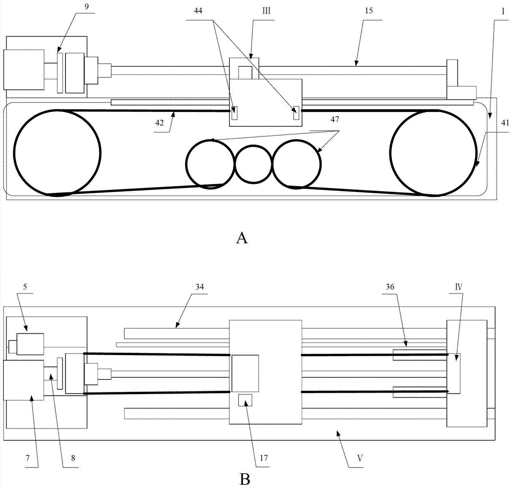
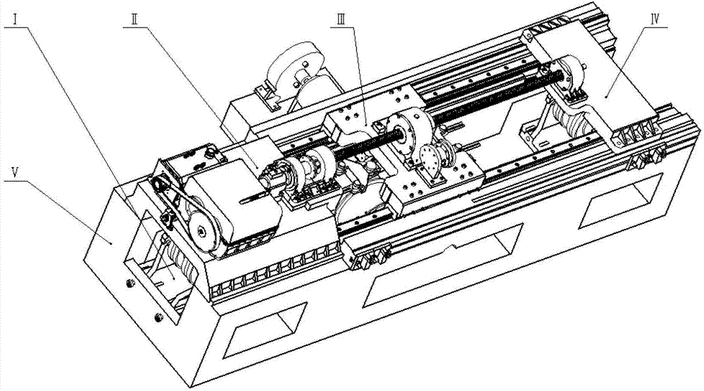
[0019] combine figure 1 , figure 2 , a ball screw pair accuracy maintenance test device of the present invention, comprising a loading part I, a headstock dragging part II, a working table part III, a tailstock supporting part IV and a bed V, wherein the headstock dragging part II and the tailstock supporting part IV are located on the bed V, the worktable part III is located between the headstock dragging part II and the tailstock supporting part IV, and the loading part I is located in the groove in the middle of the bed V;

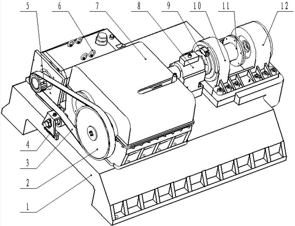
[0020] combine image 3 , the head frame dragging part II includes a head frame support plate 1, a driven pulley 2, a synchronous belt 3, a tension pulley 4, a drive pulley 5, a motor 6, a gearbox 7, a dynamic torque sensor 8, a circular magnet Grid 9, first head frame support unit 10, second head frame support unit 12, motor 6 and gearbox 7 are arranged on the head frame supporting plate 1, driving pulley 5 is arranged on the output shaft of motor 6...


PUM


Abstract

The invention discloses a ball screw assembly precision retaining ability testing device. A motor and a gearbox are arranged on a head frame supporting plate. An output shaft of the gearbox is connected with a dynamic torque sensor. The dynamic torque sensor is connected with the tested ball screw assembly through a coupling. A circular magnetic grid is arranged on the coupling. The circular magnetic grid is connected with the tested ball screw assembly. The head portion and tail portion of the tested ball screw assembly are fixed in a supporting mode through a head frame and a tail frame. An eddy current brake is connected with the gearbox and is connected with a load component. The load component comprises two duplex pulley blocks, two duplex coiling blocks and three gears. Steel wire ropes on the coiling blocks transmit damping to the nut of the tested ball screw assembly through a nut supporting board. The supporting board is fixedly connected with the matched nut of the screw assembly. Four sliding blocks are arranged on the lower sides of the two sides of the supporting board and enable the supporting board to slide on a guild rail fixed on a bed body. A tail frame supporting board is arranged on a flat-V guide rail of the tail portion of the bed body. In work, the eddy current brake provides load, through adjusting the current value passing through eddy current brake, simulation of the ball screw assembly working condition can be achieved.

Description

technical field [0001] The invention belongs to the technical field of testing the precision retention of mechanical devices, in particular to a test device for the precision retention of a ball screw pair. Background technique [0002] The ball screw has the advantages of high motion precision, small friction, no backlash, high rigidity, high reversibility for mutual conversion of rotary motion and linear motion, and high efficiency. It is a common moving part of machine tools and is widely used in various industries. equipment and precision instruments. The accuracy retention of the ball screw has a direct impact on the machining accuracy and accuracy retention of the machine tool. After the machine tool is used for a certain period of time, the raceways and steel balls will wear out, the pre-tightening force will be released, and the rolling elements will be fatigued and pitted, resulting in gap errors, resulting in axial runout out of tolerance, and affecting the machin...

Claims


Application Information

Patent Timeline
IPC IPC(8): G01M13/02
Inventor 欧屹冯虎田朱宇霖陶卫军蔡理沈嘉禾韩军王禹林殷爱华
Owner NANJING UNIV OF SCI & TECH
Why Eureka
Try Eureka