Heterodyne pulse compression type multifunctional laser radar and controlling method thereof

A pulse compression, laser radar technology, applied in the direction of electromagnetic wave re-radiation, utilization of re-radiation, measurement devices, etc., can solve the problems of incompatibility of system structure, inability to measure micro-Doppler speed, etc., to improve the maximum operating distance and simplify the structure. , reduce the effect of modulation

Inactive Publication Date: 2013-05-22
HARBIN INST OF TECH
View PDF2 Cites 8 Cited by
  • Summary
  • Abstract
  • Description
  • Claims
  • Application Information

AI Technical Summary

Problems solved by technology

[0003] The purpose of the present invention is to solve the problem that the current laser radar cannot measure speed and micro-Doppler when it realizes distance measure

Method used


Image

  • Heterodyne pulse compression type multifunctional laser radar and controlling method thereof
  • Heterodyne pulse compression type multifunctional laser radar and controlling method thereof

Examples


specific Embodiment approach 1

[0021] Specific implementation mode one: combine figure 1 Describe this embodiment, the heterodyne pulse compression type multifunctional lidar described in this embodiment,

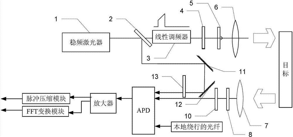
[0022] It includes a frequency-stabilized laser 1, a beam splitter 2, a chirp 3, a first polarizer 4, a first 1 / 4 wave plate 5, a transmitting antenna 6, a receiving antenna 7, a second polarizer 8, a second 1 / 4 4 wave plate 10, first mirror 11, second mirror 12, 1 / 2 wave plate 13, APD, amplifier, pulse compression module and FFT module;

[0023] On the optical axis of the laser light emitted by the frequency-stabilized laser 1, a beam splitter 2, a chirp 3, a first polarizer 4, a first 1 / 4 wave plate 5 and a transmitting antenna 6 are sequentially arranged, and the beam splitter 2 transmits The light is incident to the transmitting antenna 6 through the linear frequency modulator 3, the first polarizing plate 4, and the first 1 / 4 wave plate 5 in sequence, and is transmitted to the target through the tr...

specific Embodiment approach 2

[0027] Specific embodiment two: this embodiment is a further limitation of the heterodyne pulse compression multifunctional lidar described in specific embodiment two, the ratio of the light energy incident to the beam splitter 2 being transmitted and reflected is (9~100 ): 1.

specific Embodiment approach 3

[0028] Specific implementation mode three: combination figure 2 Describe this embodiment, this embodiment is the control method to the heterodyne pulse compression type multi-function laser radar described in specific embodiment one, it comprises the following steps:

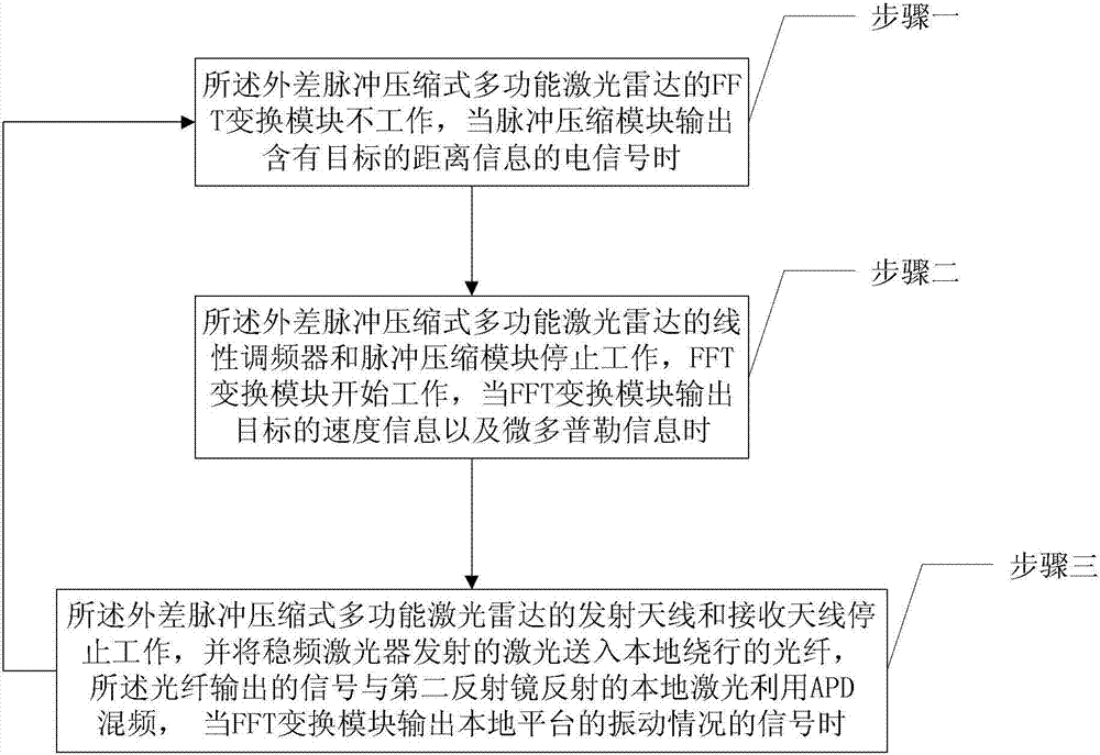
[0029] Step 1: the FFT transformation module of the heterodyne pulse compression multifunctional laser radar is not working, and when the pulse compression module outputs an electrical signal containing the distance information of the target, turn to step 2;

[0030] Step 2: the linear frequency modulator 3 and the pulse compression module of the heterodyne pulse compression multifunctional laser radar stop working, and the FFT transformation module starts to work, and when the speed information and the micro-Doppler information of the FFT transformation module output the target, turn to Enter step three;

[0031] Step 3: The transmitting antenna 6 and the receiving antenna 7 of the heterodyne pulse compressio...


PUM


Abstract

The invention discloses heterodyne pulse compression type multifunctional laser radar and a controlling method thereof, relates to laser radars, and solves the problem that existing laser radar can measure distance but cannot realize speed and micro-doppler measurement and system structure is not compatible. By the aid of the laser radar, (1) a laser signal subjected to linear frequency modulation is sent to a target, a target echo laser and a local unmodulated signal are subjected to optical frequency mixing, the frequency-mixed signal is subjected to pulse compression so as to obtain a signal containing target distance information; (2) a laser signal not subjected to linear frequency modulation is sent to the target, the target echo laser and the local unmodulated signal are subjected to optical frequency mixing, the frequency-mixed signal is subjected to FFT (fast fourier transform algorithm) conversion to obtain target speed information and micro-doppler information; and (3) a laser is sent to a local circling optical fiber, a signal output by the optical fiber and the local laser are subjected to frequency mixing, and the frequency-mixed signal is subjected to FFT conversion to obtain a vibrating state signal of a local platform. The heterodyne pulse compression type multifunctional laser radar and the controlling method are utilized to measure various information of the target.

Description

technical field [0001] The invention relates to a laser radar, in particular to a heterodyne pulse compression multifunctional laser radar and a control method thereof. Background technique [0002] It is an important research goal to measure various information of the target by laser radar, and it is still a technical problem to accurately measure the speed, distance and reflectivity information of the target at the same time, and for the needs of target recognition, it is also necessary to measure the micro-Doppler information of the target With its own vibration information, the existing lidar system cannot measure speed and micro-Doppler to achieve distance measurement, and the system structure is not compatible enough. Contents of the invention [0003] The purpose of the present invention is to solve the problem that the current laser radar cannot measure speed and micro-Doppler when it realizes distance measurement, and the system structure is not compatible enough....

Claims


Application Information

Patent Timeline
IPC IPC(8): G01S17/89G01S17/10G01S7/48
Inventor 张勇刘丽萍赵远杨成华郭瑞徐路
Owner HARBIN INST OF TECH
Why Eureka
Try Eureka