Low-loss flat transmission line

A transmission line, low-loss technology, applied in the direction of waveguide, circuit, electrical components, etc., can solve the problems of transmission line insertion loss deterioration, discontinuity, characteristic impedance deviation from 50 ohms, etc.

Active Publication Date: 2013-05-22
安费诺永亿(海盐)通讯电子有限公司
View PDF7 Cites 12 Cited by
  • Summary
  • Abstract
  • Description
  • Claims
  • Application Information

AI Technical Summary

Problems solved by technology

[0005] The purpose of the present invention is to provide a low-loss flat transmission line, especially suitable for high-frequency bands, to solve the discontinuity of the connector connecting the transmission line in the prior art, and the defect that the characteristic impedance deviates from 50 ohms occurs, resulting in transmission line Technical issue where insertion loss becomes worse at high frequencies

Method used


Image

  • Low-loss flat transmission line
  • Low-loss flat transmission line
  • Low-loss flat transmission line

Examples


Embodiment Construction

[0029] The present invention will be described in detail below in conjunction with the accompanying drawings.

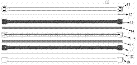
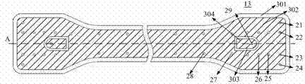
[0030] Please refer to Figures 1 to 6, a low-loss flat transmission line, including several solder resist layers used to prevent oxidation of the metal area and shield the transmission line structure from contacting the surrounding good conductors, several bonding layers for physically bonding the top and bottom layer, several dielectric layers and several connection layers for the energy transfer area. the

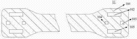
[0031] Several solder resist layers include a top layer 11 and a bottom layer 19 . The top layer 11 and bottom layer 19 are solder resist layers that prevent oxidation of the metal areas and shield the transmission line structure from contact with surrounding good conductors.

[0032] The bonding layer has two layers, one of which is located below the top layer, and the other is located above the bottom layer. That is, the middle layer 12 and the middle layer...


PUM


Abstract

A low-loss flat transmission line comprises a plurality of solder mask layers, a plurality of bonding layers, a plurality of dielectric layers and a plurality of connecting layers, wherein the solder mask layers are used for preventing oxidization of a metal area and contact of a shielded transmission line structure and a peripheral good conductor, the bonding layers are used for physical vertical bonding, and the dielectric layers are used for an energy transmission area. A first signal pad and a first gap surrounding the first signal pad are arranged on at least one end of the first connecting layer, at least one signal line via hole is arranged on the first signal pad, a signal transition area and a plurality of gaps on the signal transition area are arranged on at least one end of the second connecting layer, a second signal pad and a second gap surrounding the second signal pad are arranged on at least one end of the third connecting layer, the signal line via holes of the first connecting layer are communicated with signals of the first signal pad, the second signal pad and the signal transition area, and the signal transition area is connected with signal lines. By the aid of the connecting structure, L1 and C1 are optimized, the influence of discontinuity is greatly reduced, and insertion loss of the transmission line structure is furthest reduced.

Description

technical field [0001] The invention relates to a communication antenna, in particular to a low-loss flat transmission line related to the communication antenna. Background technique [0002] An antenna is a device that uses frequency characteristics to receive and transmit signals. In recent years, the design and performance of mobile terminal antennas for wireless communication have more and more influence on the development direction of mobile communication. Especially portable mobile terminals such as mobile phones, PDA (Personal Digital Assistance), MP3 / MP4. The main indicators of the antenna design are: there is a suitable multi-frequency resonance, and the antenna realizes signal propagation and energy radiation based on the resonance of a certain frequency. If an antenna can resonate at multiple frequencies, then the antenna will work at multiple frequencies. [0003] In recent years, more and more wireless terminals adopt a low-profile structural design. That i...

Claims


Application Information

Patent Timeline
Patent Type & Authority Applications(China)
IPC IPC(8): H01P3/18
CPCH01P3/08H01P3/18H01P3/085
Inventor 孙劲何其娟李立忠
Owner 安费诺永亿(海盐)通讯电子有限公司
Why Eureka
Try Eureka