A Speed ​​Sensorless Estimation Method for High Precision Permanent Magnet Synchronous Motor

A permanent magnet synchronous motor and speed sensorless technology, which is applied in the control of generators, motor generators, electromechanical brakes, etc., can solve problems such as slow dynamic characteristics and complex principles

Active Publication Date: 2015-08-26
DONGFANG ELECTRIC CORP LTD
View PDF8 Cites 0 Cited by
  • Summary
  • Abstract
  • Description
  • Claims
  • Application Information

AI Technical Summary

Problems solved by technology

[0015] In order to overcome the problems of the existing speed sensorless permanent magnet synchronous motor rotor angle and speed estimation method, the principle is complex and the slow dynamic characteristics,...

Method used


Image

  • A Speed ​​Sensorless Estimation Method for High Precision Permanent Magnet Synchronous Motor
  • A Speed ​​Sensorless Estimation Method for High Precision Permanent Magnet Synchronous Motor
  • A Speed ​​Sensorless Estimation Method for High Precision Permanent Magnet Synchronous Motor

Examples


Embodiment 1

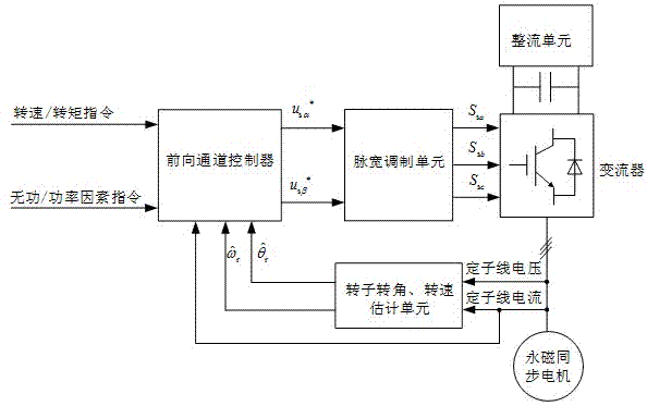
[0067] figure 1 It is a typical system block diagram of an existing speed sensor-based permanent magnet synchronous motor. The controlled object is a permanent magnet synchronous motor, and the actuator is a converter. The rectification unit rectifies the grid voltage and maintains the DC bus voltage of the converter constant, thereby ensuring the normal operation of the converter. The control system mainly includes three parts, the forward channel controller, the pulse width modulation unit and the rotor angle and speed estimation unit. The forward channel controller receives the given speed / torque command and reactive power / power factor command, and controls the stator voltage at Components in the Coordinate System . PWM unit pair Modulate to generate the switching signals required by the converter , and then drive the permanent magnet synchronous motor. The rotor angle and speed estimation unit is located on the feedback channel, extracts the rotor angle and spee...

Embodiment 2

[0111] In this embodiment, the method for estimating the rotor angle and rotational speed of the permanent magnet synchronous motor provided by the present invention is applied to a direct-drive wind power generation system based on a permanent magnet synchronous motor. The main parameters of the direct drive permanent magnet synchronous wind power generation system are as follows:

[0112]

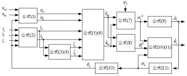
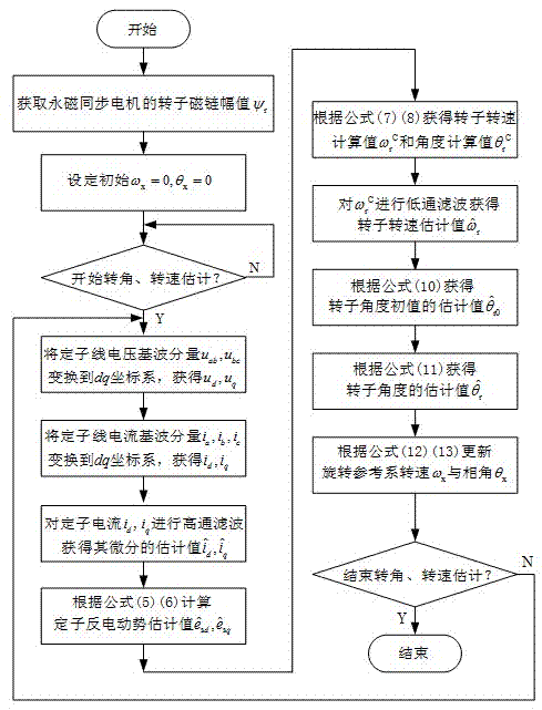
[0113] Firstly, the amplitude of the rotor flux linkage of the permanent magnet synchronous motor It can be calculated from the rated parameters: . Then, follow figure 2 The structure shown in the present invention is used to realize the method for estimating the rotor angle and rotational speed of the permanent magnet synchronous motor proposed by the present invention. Among them, the high-pass filter According to the design of the first-order high-pass filter link, the time constant is taken as ,Right now . low pass filter All are designed according to the first-order...


PUM


Abstract

The invention relates to the technical field of electric derive and control, in particular to a without-speed sensor estimation method for a high-accuracy permanent magnet synchronous motor. An estimation process is finished in an estimation rotation reference system with rotate speed being wx and with a phase angle being thetax. The method comprises the steps of firstly, conducting low-pass filtering for a rotate speed calculated value through a formula, obtaining a rotate speed estimation value, eliminating an algebra loop on the rotate speed, meanwhile, finishing estimation of a rotor angle initial value through a formula, then, combining a formula, finishing estimation of an angle through the fact that estimation of the rotor angle initial value is added to an angle integral value, and finally adopting and updating the rotate speed and the phase angle of the estimation rotation reference system so that influence due to a high-pass filtering step is reduced, and therefore estimation accuracy is improved. The without-speed sensor estimation method for the high-accuracy permanent magnet synchronous motor has the advantages of being conducted in the rotation reference system. Compared with an estimation method in a stationary coordinate system, the without-speed sensor estimation method for the high-accuracy permanent magnet synchronous motor is smaller in influence due to the high-pass filtering step, and therefore the estimation accuracy is higher.

Description

technical field [0001] The invention relates to the technical field of electric transmission and control, and specifically relates to a speed sensorless estimation method of a permanent magnet synchronous motor. Background technique [0002] The permanent magnet synchronous motor does not need an excitation mechanism, has a simple structure, high energy density, and reliable performance. In recent years, it has been widely used in wind power generation, electric vehicles, ship drives and other fields. At present, the control of permanent magnet synchronous motor usually adopts the speed sensorless control method. The speed sensorless control system eliminates the traditional speed sensor, thus has higher system reliability and lower cost, and also has the advantages of small system size, light weight, and simple connection between the motor and the controller . Since the speed sensorless control system does not install a speed sensor, it is necessary to detect the stator c...

Claims


Application Information

Patent Timeline
IPC IPC(8): H02P21/14H02P21/18H02P21/24
Inventor 周宏林代同振于海坤况明伟吴建东
Owner DONGFANG ELECTRIC CORP LTD
Why Eureka
Try Eureka