Steel ball casting die

A technology for casting molds and steel balls, applied in the field of steel ball casting molds, can solve problems such as short pouring time, and achieve the effects of short pouring time, reduced labor intensity, and improved product finish.

Inactive Publication Date: 2013-05-29
仇存红
View PDF0 Cites 15 Cited by
  • Summary
  • Abstract
  • Description
  • Claims
  • Application Information

AI Technical Summary

Problems solved by technology

[0003] In order to solve the above problems, the present invention proposes a new type of steel ball casting mold. The mold does not need to be manually moved during use, which reduces the labor intensity of workers and greatly improves the utilization rate of molten steel, which can reach 93%. The smoothness of the product has been greatly improved, and the finished steel ball has no sand falling and gas ring phenomenon, and the pouring time is short

Method used


Image

  • Steel ball casting die
  • Steel ball casting die

Examples


Embodiment Construction

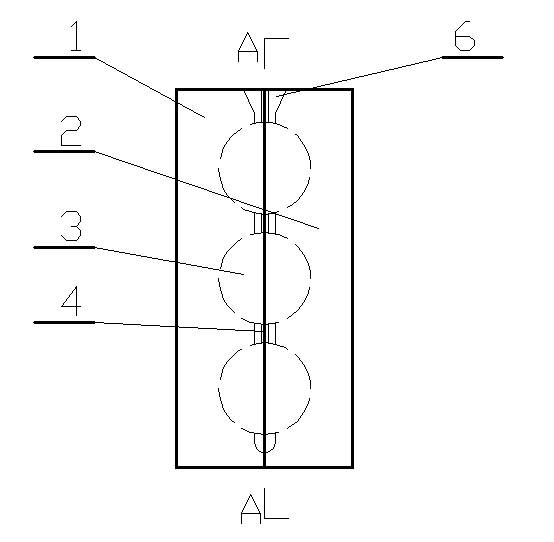
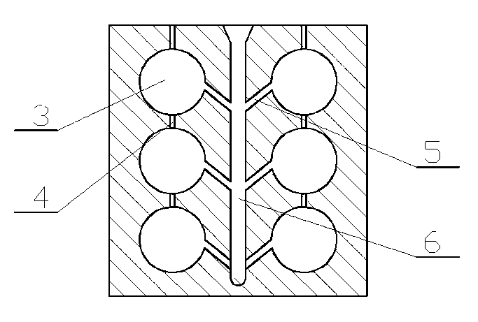
[0013] In the accompanying drawings, the steel ball casting mold includes two half molds. The mold adopts the mode of left and right mold closing. The bonding surfaces of the two half molds are correspondingly provided with a plurality of semicircular ball grooves 3 from top to bottom. When the two half-moulds are closed, two semicircular ball grooves 3 form a complete ball groove 3; the upper and lower adjacent ball grooves 3 are communicated by an air groove 4; one side of the ball groove 3 is provided There is a vertical runner 6, and the runner 6 and the ball groove 3 are connected by a pouring branch 5.

[0014] The air outlet of the air groove 4 and the pouring port of the runner 6 are all arranged on the top of the mould.

[0015] The air groove 4, the runner 6 and the pouring branch 5 are divided into two parts longitudinally and symmetrically with the connecting surfaces of the left and right half molds as the midline, and are respectively arranged on the left half mo...


PUM


Abstract

The invention relates to a steel ball casting die. The steel ball casting die comprises two half dies, wherein the die adopts a left-right die assembly manner, and the faying surface of the two half dies is correspondingly provided with multiple half round ball grooves from top to bottom; when the two half dies are closed, the two half round ball grooves can form an integrated ball groove; the adjacent upper and lower ball grooves are communicated through an air groove; one sides of the ball grooves are provided with vertical pouring gates, and the pouring gates and the ball grooves are connected through a pouring branch channel; and air outlets of the air grooves and pouring ports of the pouring gates are formed in the top of the die. The steel ball casting die does not need to move through people in a using process, the labour intensity of workers is lightened, the molten steel use ratio is greatly improved and can achieve 93%, the product fineness is greatly improved, the finished steel ball has no sand falling and air ring, and the pouring time is short.

Description

technical field [0001] The invention relates to a mold, in particular to a steel ball casting mold. Background technique [0002] Steel balls need to use molds in the production process. Traditional molds need to be sanded first when pouring. When sanding, the mold moves more times, and the utilization rate of molten steel is low, the finish of the finished product is low, and the sand falling phenomenon is serious. And the pouring time is longer. Contents of the invention [0003] In order to solve the above problems, the present invention proposes a new type of steel ball casting mold. The mold does not need to be manually moved during use, which reduces the labor intensity of workers and greatly improves the utilization rate of molten steel, which can reach 93%. The smoothness of the product has been greatly improved, and the finished steel ball has no falling sand and gas ring phenomenon, and the pouring time is short. [0004] The present invention is achieved throu...

Claims


Application Information

Patent Timeline
Patent Type & Authority Applications(China)
IPC IPC(8): B22C9/20B22C9/08
Inventor 仇存红
Owner 仇存红
Why Eureka
Try Eureka