Design method for optimal damping ratio of suspension system of cab

A technology of optimal damping ratio and optimal damping ratio, applied in the superstructure, superstructure, transportation and packaging of trucks, etc., can solve the problems such as the design requirements that cannot meet the comfort of the vehicle cab

Inactive Publication Date: 2013-05-29
SHANDONG UNIV OF TECH
View PDF2 Cites 28 Cited by
  • Summary
  • Abstract
  • Description
  • Claims
  • Application Information

AI Technical Summary

Problems solved by technology

With the rapid development of the automobile industry, the current damping ratio design method of t

Method used


Image

  • Design method for optimal damping ratio of suspension system of cab
  • Design method for optimal damping ratio of suspension system of cab
  • Design method for optimal damping ratio of suspension system of cab

Examples


Embodiment 1

[0049] Example 1: Mounting of a truck cab, where one-side mounting corresponds to the quality of the cab kg, the cab mount elastic coefficient corresponding to one side mount N / m; car body mass corresponding to a single wheel kg, the sprung mass, the suspension spring stiffness N / m, suspension damping coefficient N.s / m; unsprung mass kg, tire stiffness N / m; Class C pavement reference spatial frequency m -1 The pavement power spectral density value under m 3 , the vehicle speed km / h; vertical displacement coordinates of wheels, body and cab , and ;Input road roughness function .

[0050] The optimal damping ratio design process of the cab mount provided by the present invention is as follows: figure 2 As shown, the specific steps are as follows:

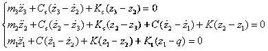
[0051] (1) Determine the vertical vibration acceleration frequency response function of the cab and wheel dynamic load frequency response function :

[0052] According to the cab quality corresponding ...

Embodiment 2

[0083] Embodiment two : One-side suspension mass of a truck cab kg, elastic coefficient of one side suspension N / m; Other parameters are identical with embodiment one. Adopt the design steps of embodiment one, namely:

[0084] (1) Determine the vertical vibration acceleration frequency response function of the cab and wheel dynamic load frequency response function :

[0085] According to the quality of one side suspension of a truck cab kg, the elastic coefficient of one-side suspension of the cab N / m; car body mass corresponding to a single wheel kg, the sprung mass, the suspension spring stiffness N / m, suspension damping coefficient N.s / m; unsprung mass kg, tire stiffness N / m; vertical displacement coordinates of wheels, body and cab , and ;Input road roughness function ;According to the vehicle parameters and the driving vibration differential equation, determine the frequency response function of the vertical vibration acceleration of the ca...


PUM


Abstract

The invention belongs to the technical field of suspension of cabs, and relates to a design method for an optimal damping ratio of a suspension system of a cab. No design method for the optimal damping ratio of the suspension system of the cab exists domestically or overseas nowadays. The design method for the optimal damping ratio of the suspension system of the cab is characterized in that an iterated integral of the matrix laboratory (Matlab) is used for building an objection function of vertical vibration acceleration of the cab and wheel dynamic loads according to cab vibration acceleration and a wheel dynamic load response function of a wheel, a vehicle body and a cab three mass vibration system, the optimal damping ratio, based on comfort, of the suspension system of the cab, and the optimal damping ratio, based on safety, of the suspension system of the cab are respectively calculated, and then the optimal damping ratio of the suspension system of the cab is designed. Through the design method for the optimal damping ratio of the suspension system of the cab, for different vehicle parameters, cab parameters, vehicle types, driving road conditions and the speed of vehicles, an accurate and reliable optimal damping ratio of the suspension system of the cab can be obtained, the best shock absorbing effect of the cab can be realized, repeated verification and modification are avoided, the development cycle is shortened, and design and experimental expenses are reduced.

Description

technical field [0001] The invention relates to a truck cab mount, in particular to a design method for the optimum damping ratio of the cab mount. Background technique [0002] Many trucks use a cab suspension system, which refers to a suspension system that uses coil springs, leaf springs or air springs as elastic support elements and hydraulic shock absorbers as damping elements to obtain a larger stroke. Since the cab suspension system belongs to the three-mass vibration system (wheel mass, body mass and cab mass), its analysis and calculation are very complicated. Many experts in vehicle engineering at home and abroad have to use a simplified single-mass vibration system model for analysis. The vehicle body vibration is regarded as the excitation input of the cab vibration, therefore, only an approximate design value of the damping ratio of the cab suspension system can be given. According to the information we have consulted, at present domestic and foreign vehicle en...

Claims


Application Information

Patent Timeline
IPC IPC(8): B62D33/10
Inventor 周长城孔艳玲刘小亭
Owner SHANDONG UNIV OF TECH
Why Eureka
Try Eureka