Suspended ceiling light steel subsidiary keel and method of assembling suspended ceiling light steel subsidiary keel in special-shaped suspended ceiling

A technology of auxiliary keel and light steel, applied in the field of keel, can solve the problems of inability to achieve rapid installation, weak installation, poor positioning, etc., and achieve the effect of being conducive to firm engagement, good positioning effect, and material saving

Inactive Publication Date: 2013-05-29
马自力
View PDF7 Cites 14 Cited by
  • Summary
  • Abstract
  • Description
  • Claims
  • Application Information

AI Technical Summary

Problems solved by technology

[0002] In the construction of architectural decorative ceilings, for example, there will be a large number of special-shaped ceilings in the ceiling. It is necessary to connect the light steel sub-keels of the ceiling to make the ceiling basic structure. There are no special connectors for the connection of special-shaped structures between the traditional light-steel sub-keels of the ceiling. It can only be connected by inserting wood into the auxiliary keel or processing the shape of the end of the keel, which cannot be installed quickly and is not firm after installation
In recent years, there have also been connectors that realize the special-shaped connection between the light steel sub-keels of the ceiling, but because the side walls of the light steel sub-keels of the ceiling are flat, this kind of connector and the light-steel sub-keel of the ceiling are in plane contact, and the positioning is not good. Accurate, easy to misplace, and not strong

Method used


Image

  • Suspended ceiling light steel subsidiary keel and method of assembling suspended ceiling light steel subsidiary keel in special-shaped suspended ceiling
  • Suspended ceiling light steel subsidiary keel and method of assembling suspended ceiling light steel subsidiary keel in special-shaped suspended ceiling
  • Suspended ceiling light steel subsidiary keel and method of assembling suspended ceiling light steel subsidiary keel in special-shaped suspended ceiling

Examples


Embodiment Construction

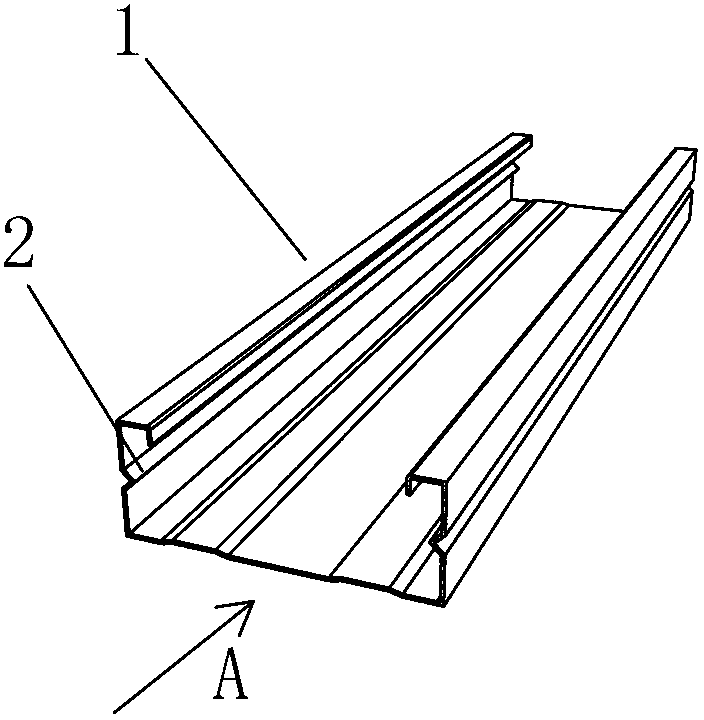
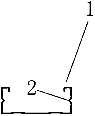
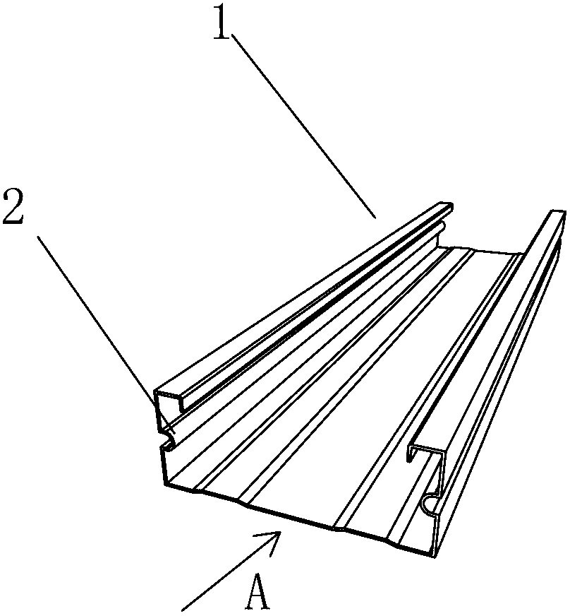
[0033] Such as Figure 1-Figure 6 As shown, the present invention is a light steel auxiliary keel for a suspended ceiling, which is mainly used in special-shaped suspended ceilings. The two side walls of the light steel auxiliary keel 1 for the suspended ceiling each have a grooved rib 2 for positioning. Groove rib 2 is for positioning when the light steel sub-keel of the suspended ceiling is connected with other parts to be connected.

[0034] When assembling, a connecting piece is used, and the connecting piece has corresponding strip grooves adapted to the grooved bars of the light steel auxiliary keel of the suspended ceiling, so as to realize positioning.

[0035] Compared with the previous method of directly achieving plane contact on the plane side wall by means of screws or the like, the present invention obviously has a better positioning effect, is more accurate and faster, and greatly improves the construction speed. It is worth mentioning that the light steel sub-...


PUM


Abstract

Provided is a suspended ceiling light steel subsidiary keel. Side walls on two sides of the light steel subsidiary keel are respectively provided with one groove type rib. The invention further relates to a method of assembling the light steel subsidiary keel in a special-shaped suspended ceiling. According to the method of assembling the light steel subsidiary keel in the special-shaped suspended ceiling, a connection piece is needed to be matched. Strip-shaped grooves which are matched with the groove type ribs of the light steel subsidiary keel are formed in corresponding positions of the connection piece. The connection piece is inserted into a light steel keel and the light steel subsidiary keel, is positioned through the groove type ribs and the strip-shaped grooves in an insertion-connection mode and finally fixes the light steel keel and the light steel subsidiary keel through the connection piece. Compared with a previous screw fixation mode, the suspended ceiling light steel subsidiary keel and the method of assembling the suspended ceiling light steel subsidiary keel in the special-shaped suspended ceiling are good in fixing effect, capable of improving the construction speed, free from requirements of adding spare parts and auxiliary structures, low in cost, firm in connection and free from dislocation.

Description

technical field [0001] The invention relates to a keel, in particular to a light steel auxiliary keel for a suspended ceiling and a method for assembling the light steel auxiliary keel for a suspended ceiling in a special-shaped suspended ceiling. Background technique [0002] In the construction of architectural decorative ceilings, for example, there will be a large number of special-shaped ceilings in the ceiling. It is necessary to connect the light steel sub-keels of the ceiling to make the ceiling basic structure. There are no special connectors for the connection of special-shaped structures between the traditional light-steel sub-keels of the ceiling. It can only be connected by inserting wood into the auxiliary keel or processing the shape of the end of the keel, which cannot be installed quickly and is not firm after installation. In recent years, there have also been connectors that realize the special-shaped connection between the light steel sub-keels of the cei...

Claims


Application Information

Patent Timeline
Patent Type & Authority Applications(China)
IPC IPC(8): E04B9/06E04B9/10E04B9/12E04G21/14
CPCE04B9/12E04B9/06E04B9/127E04B9/30E04C2003/0473
Inventor 田军峰蔡金河邹雪松
Owner 马自力
Why Eureka
Try Eureka