LED linear intelligent dimming module

An intelligent dimming and linear technology, applied in the direction of light source, electric light source, energy-saving control technology, etc., can solve the problems of difficulty in adapting to thyristor dimming, complexity, and many LED drive module components, etc., and achieve simple constant current switching function, Simplified circuit and good consistency

Active Publication Date: 2013-05-29
XIAMEN HI LIGHT LIGHTING +2
View PDF5 Cites 8 Cited by
  • Summary
  • Abstract
  • Description
  • Claims
  • Application Information

AI Technical Summary

Problems solved by technology

[0004] Aiming at the problem that the existing LED drive module has many components, is complex and is difficult to adapt to the dimming of the thyristor, the present invention proposes an LED linear intelligent dimming module, and its technical scheme is as follows:

Method used


Image

  • LED linear intelligent dimming module
  • LED linear intelligent dimming module
  • LED linear intelligent dimming module

Examples


Embodiment 1

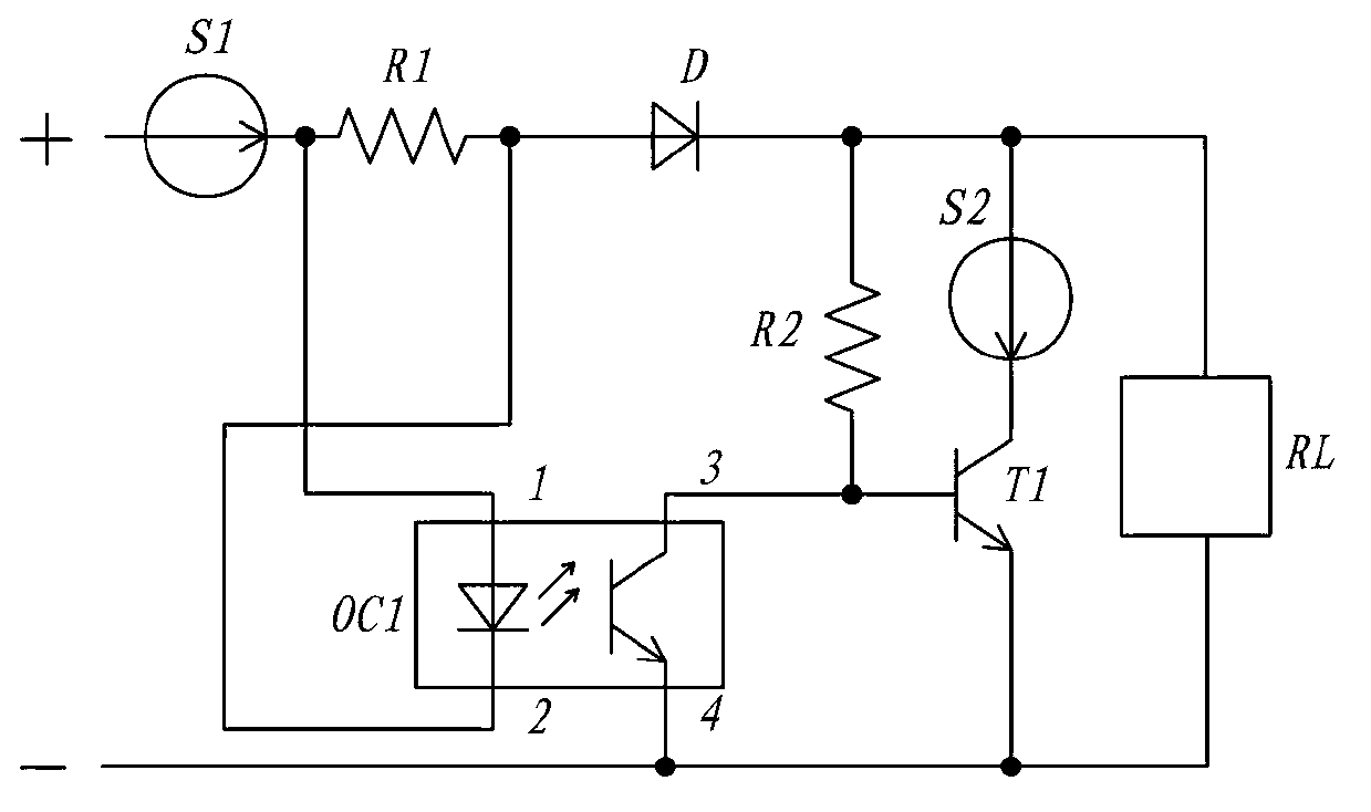
[0026] Such as figure 1 Shown is a schematic circuit diagram of Embodiment 1 of the present invention.

[0027] The dimming module includes a load circuit, a current expansion branch and a trigger optocoupler for controlling the current expansion branch. The load circuit is connected between the positive and negative poles of the power supply. It includes a main constant current source S2, a sampling resistor R1, a diode D and a load RL in sequence. The components with polarity in the load circuit are all according to the current The flow direction is forward in series. Wherein, the load RL includes an LED light source.

[0028] There is another expansion branch, which includes a sub-constant current source S2, a drive tube T1 and a bias resistor R2, wherein the sub-constant current source S2 is forwardly connected in series with the CE pole of the drive tube T1 , and then overall connected in parallel to both ends of the load RL; the bias resistor R2 is connected between t...

Embodiment 2

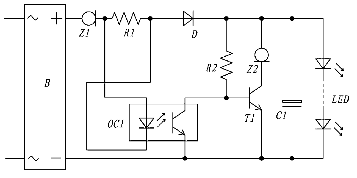
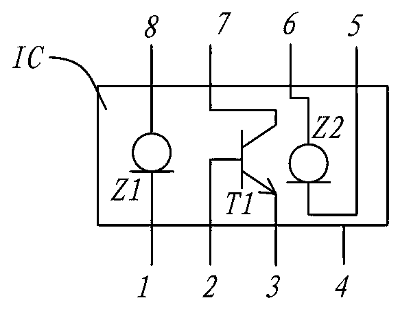
[0036] Such as figure 2 and image 3 Shown is a schematic diagram of Embodiment 2 of the present invention.

[0037] The load of this embodiment includes a series LED light source group and an electrolytic capacitor C1 connected in parallel with the LED light source group, and integrates a rectifier bridge B, the positive and negative poles of the power supply are connected to the positive and negative poles of the rectifier bridge B, and the rectifier The AC end of the bridge B is connected to the output end of the dimmer (not marked), that is, it is directly replaced and connected to the original dimming circuit.

[0038] In this embodiment, the main constant current source and the negative constant current source are constant current diodes Z1 and Z2 respectively. The forward volt-ampere characteristic of the constant current diode is used to realize a very simple structure with constant current source conduction and constant current switching functions, and has a cost a...


PUM


Abstract

The invention discloses an LED linear intelligent dimming module which is characterized by comprising a load circuit, a current expansion branch circuit and a trigger optical coupler, wherein the load circuit is connected between a positive electrode and a negative electrode of a power supply and sequentially comprises a main constant current source, a sampling resistor, a diode and a load which are forwardly connected in series, the current expansion branch circuit comprises an auxiliary constant current source, a driving tube and a biasing resistor, the auxiliary constant current source is forwardly connected in series with a CE electrode of the driving tube and then integrally connected in parallel with the load, the biasing resistor is connected between a positive electrode of the load and a B electrode of the driving tube, ends 1 and 2 of a luminous tube of the trigger optical coupler are forwardly connected in parallel with the sampling resistor, and ends 3 and 4 of a transistor of the trigger optical coupler are connected with the B electrode and an E electrode of the driving tube respectively. The LED linear intelligent dimming module realizes dimming and constant current adaption functions, the load can be connected with a traditional silicon controlled rectifier dimmer, the LED linear intelligent dimming module has a quite simple circuit, coil components such as an inductor and a transformer are omitted, and material cost is low.

Description

technical field [0001] The invention relates to a lighting driving device, in particular to a driving module for LED lighting. Background technique [0002] LED lamps have been widely used in the lighting industry: the driving technology of LED indoor lighting lamps is changing with each passing day. At present, most of the drivers of indoor LED lighting lamps are large-scale use of highly integrated switching power supply, and coil devices such as inductors and transformers are used. The price remains high, the structure is complicated, and the installation is difficult. development of. Considering that a large number of LED lamps must enter the consumer market in large quantities and directly replace traditional lamp light sources, its price positioning is acceptable to the public, which is an inevitable goal. However, in the current switching power supply scheme, the above-mentioned components are more It is very difficult to achieve parity in the drive circuit of the c...

Claims


Application Information

Patent Timeline
Patent Type & Authority Applications(China)
IPC IPC(8): H05B37/02
CPCH05B37/02Y02B20/48H05B45/10H05B45/345H05B45/395Y02B20/30
Inventor 连宗山吴金水马文军许志华
Owner XIAMEN HI LIGHT LIGHTING
Why Eureka
Try Eureka