Wire drawing head of filler cap and automobile

A fuel filler cap and thread head technology, which is applied to vehicle components, superstructure, and subassembly of the superstructure, etc., can solve the problems of difficult installation, affecting production rhythm, and prone to potential safety hazards, so as to avoid potential safety hazards and improve visibility. The effect of avoiding hand cuts

Active Publication Date: 2013-06-05
CHERY AUTOMOBILE CO LTD
View PDF5 Cites 1 Cited by
  • Summary
  • Abstract
  • Description
  • Claims
  • Application Information

AI Technical Summary

Problems solved by technology

[0005] In order to solve the problems of difficult installation in the prior art, affecting the production cycle, and prone to potential safety hazards, the embodiment of the present invention provides a fuel filler cap cable head and an automobile

Method used


Image

  • Wire drawing head of filler cap and automobile
  • Wire drawing head of filler cap and automobile
  • Wire drawing head of filler cap and automobile

Examples


Embodiment 1

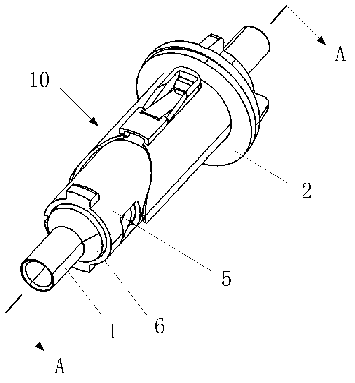
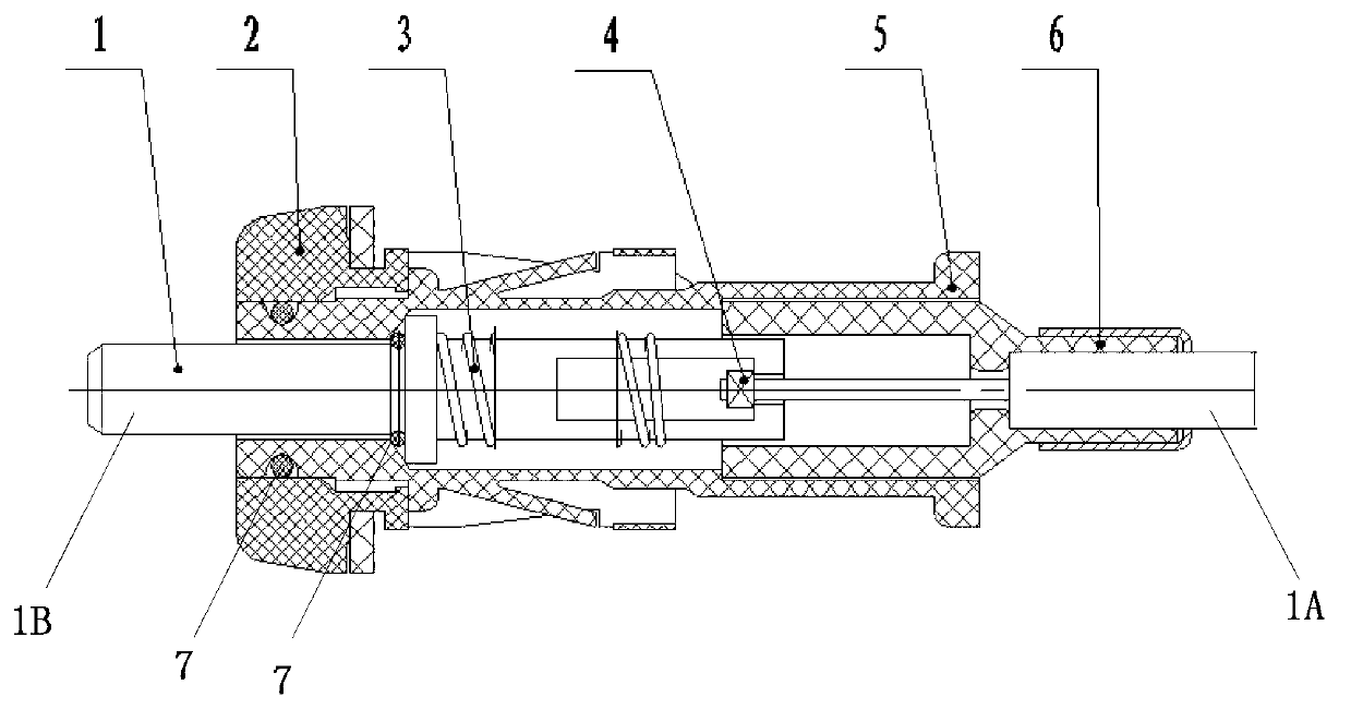
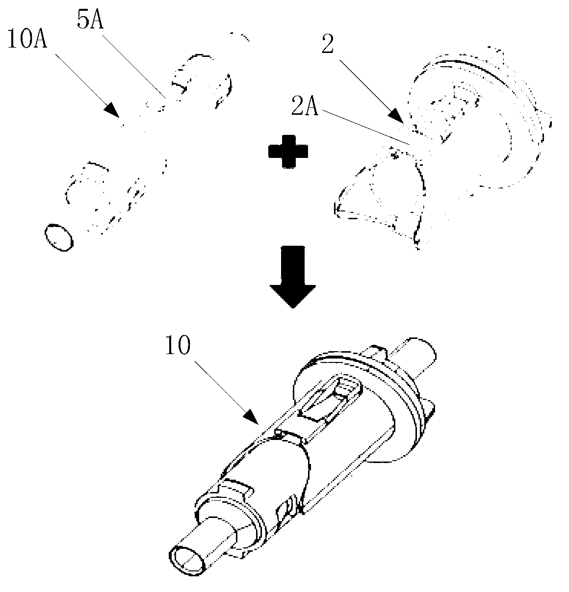
[0032] Such as figure 1 shown, see also figure 2 and image 3 , the embodiment of the present invention takes figure 1 To illustrate the main purpose, the present invention provides a fuel filler cap puller 10, which includes: a pillar 1, a rivet 4 (see figure 2 ), tower 6, compression spring 3 (see figure 2 ), tower cover 5 and sheath 2, the rivets 4 (see figure 2 ) from one end of the strut 1A (see figure 2 ) into and riveted, the rivets 4 (see figure 2 ) is used to drive the pillar 1 to do linear motion, and the rivet 4 (see figure 2 ) and the strut end 1A (see figure 2 ) is sleeved on the outside of the tower 6, the tower 6 is used to support the tower cover 5, the tower 6 is used to limit the movement position of the pillar 1, the pillar 1 and the tower 6 is provided with said compression spring 3 (see figure 2 ), the compression spring 3 (see figure 2 ) is used to reset the pillar 1, the tower base 6 and the other end 1B of the pillar (see figure 2 ...

Embodiment 2

[0044] Such as Figure 4 As shown, the present invention also provides a kind of automobile, and described automobile comprises fuel filler box 20, also comprises described fuel filler cap pull wire 10, and described fuel filler cap pull wire 10 is installed on the described fuel filler by exterior Box 20 on. Wherein, the specific structure of the fuel filler cap pull wire 10 is exactly the same as that of the fuel filler cap pull wire 10 in the first embodiment, and the specific structure of the fuel filler cap pull wire 10 will not be repeated in this embodiment.

[0045] see Figure 4 , because the fuel filler cap puller 10 can be installed in the car as an exterior, it effectively improves the visibility during installation, makes the installation easy, improves the production cycle, and can effectively avoid cuts on the hands of the installers. and other safety hazards, and then make the automobile with the fuel filler cap pull wire 10, the on-site assembly efficiency i...


PUM


Abstract

The invention discloses a wire drawing head of a filler cap and an automobile and belongs to the field of automobiles. The wire drawing head of the filler cap comprises a support, a rivet, a tower base, a compressed spring, a tower shade and a sheath, wherein the rivet extends into the wire drawing head from one end of the support and is fixedly riveted, the tower base is connected onto the outer portion of the rivet and one end of the support in sleeved mode and is used for supporting the tower shade, the compressed spring is arranged between the support and the tower base, the tower shade is connected onto the other end of the tower base and the other end of the support in sleeved mode, the sheath is connected onto the outer portion of the tower shade in sleeved mode, and an elastic reverse clamping structure is arranged between the sheath and the tower shade. The automobile comprises the filler cap and the wire drawing head of the filler cap, wherein the wire drawing head of the filler cap is externally arranged on the filler cap. The wire drawing head of the filler cap effectively improves visibility during installation, leads installation to be easy, improves production takt, and can effectively avoid potential safety hazards such as hand cutting of the installation personnel. In addition, the wire drawing head of the filler cap has the advantages of being simple in integral structure and high in reliability.

Description

technical field [0001] The invention relates to the field of automobiles, in particular to a fuel filler cap puller and an automobile. Background technique [0002] At present, automobiles usually use fuel filler cap pull wires to control the switch of the fuel filler cap. [0003] The traditional fuel filler cap cables are built-in assemblies. Internal installation refers to the installation method of directly fixing and installing the fuel filler cap cable head on the fuel filler cap from the car. Wherein, the fuel filler cap pull wire includes a fuel filler cap pull wire head. [0004] The structure of the existing fuel filler cap cable head is designed according to the built-in installation method. Due to the limitation of this structure, the visibility is poor at the on-site loading station, and it is difficult for one person to install the fuel filler cap cable. Not only is the installation difficult , affecting the production beat, and prone to safety hazards such ...

Claims


Application Information

Patent Timeline
Patent Type & Authority Applications(China)
IPC IPC(8): B62D25/24
Inventor 李志陈勇袁堂福温秀海朱志军
Owner CHERY AUTOMOBILE CO LTD
Why Eureka
Try Eureka