Friction disks of clutch

A friction disc and clutch technology, applied in the field of friction discs, can solve the problem of increased inertia power loss of clutches, and achieve the effect of reducing the structure size

Inactive Publication Date: 2013-06-05
SCHAEFFLER TECH AG & CO KG
View PDF12 Cites 2 Cited by
  • Summary
  • Abstract
  • Description
  • Claims
  • Application Information

AI Technical Summary

Problems solved by technology

Therefore, as the power increases, the friction disks must be constructed with a correspondingly greater mass, whereby the inertia of the clutch and thus the power losses also increase

Method used


Image

  • Friction disks of clutch
  • Friction disks of clutch
  • Friction disks of clutch

Examples


Embodiment Construction

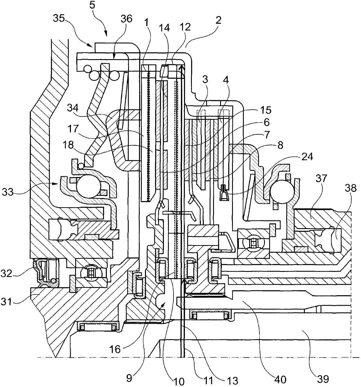
[0036] figure 1 The clutch 5 is shown here as a double clutch and has a central web 2 with internally cooled friction disks—here first pressure plate 1 , central web 2 , second pressure plate 3 and third pressure plate Compression plate 4. Arranged between the first pressure plate 1 and the central web 2 is a first clutch disc 6 , which is connected to a first transmission shaft 39 . A second clutch disk 7 is arranged between the second pressure plate 3 and the central web 2 , and a third clutch disk 8 is arranged between the third pressure plate 4 and the second pressure plate 3 . The second clutch disk 7 and the third clutch disk 8 are jointly connected to the second transmission shaft 40 . All friction disks shown have a through hole in the center 9 . An inner edge 10 with an inner diameter 11 is thus formed on the side directed toward the center 9 . An outer edge 12 with an outer diameter 13 is formed on the maximum radial extent of the friction disk. As an example, a...


PUM


Abstract

The invention relates to friction disks of a clutch. The friction disks are used for transmitting a pressing force to one or two adjacent friction discs in a friction fitting manner, wherein the friction disks have one center, an inner edge provided with an inner diameter, an outer edge provided with an outer diameter and two lateral functional surfaces. The friction disks are characterized in that at least one friction disk is provided with a channel between the two lateral functional surfaces; the channel can allow flow fluid to pass through. With the described friction disks and the clutch with the described friction disks, problems in a conventional technology can be solved maximally. Particularly, the friction disk make it possible to construct the clutch with less heat mass, wherein power loss is reduced and structure size can be minimized.

Description

technical field [0001] The invention relates to a friction disk for a clutch for the frictional transmission of a pressing force to one or two adjacent friction disks. Background technique [0002] Various friction disks are known from the prior art for the production of clutches. Usually, pressure plate and clutch plate and, in the case of a double clutch arrangement, the central web are referred to as friction plates. In clutches, in particular for motor vehicle construction, high torques are transmitted via relatively movable friction disks by frictionally connecting the friction disks by means of a pressing force. In order not to overload the components of such clutches due to the heat generated, the friction disks must be designed with a corresponding thermal mass. Consequently, as the power increases, the friction disks have to be constructed with a correspondingly greater mass, whereby the inertia of the clutch and thus the power losses also increase. Contents of ...

Claims


Application Information

Patent Timeline
Patent Type & Authority Applications(China)
IPC IPC(8): F16D69/00F16D13/72
CPCF16D2021/0684F16D13/64F16D13/385F16D25/10F16D13/72F16D25/082F16D21/06
Inventor E·洛伦茨
Owner SCHAEFFLER TECH AG & CO KG
Why Eureka
Try Eureka