
Resistance test method

A technology for resistance testing and resistance to be tested, which is applied in the direction of measuring resistance/reactance/impedance, measuring devices, and measuring electrical variables, etc. It can solve the problems of increasing the detection time of enterprises, cumbersome testing methods, and consuming manpower and material resources, and achieve simple testing methods Fast, saves manpower and material resources, and saves testing time

Active Publication Date: 2013-06-05
SHANGHAI HUALI MICROELECTRONICS CORP
View PDF10 Cites 5 Cited by
  • Summary
  • Abstract
  • Description
  • Claims
  • Application Information

AI Technical Summary

Problems solved by technology

[0013] It can be seen that due to the relative independence of each resistance test circuit in the prior art, the traditional test method is cumbersome, and a resistance to be tested needs to use two test pads. During the test, it is also necessary to test the pads in each test circuit. The voltage and current in the circuit are more troublesome, which increases the detection time of the enterprise and consumes a lot of manpower and material resources

Method used


Image

  • Resistance test method
  • Resistance test method
  • Resistance test method

Examples


Embodiment Construction

[0028] The present invention will be further described below in conjunction with the accompanying drawings and specific embodiments, but not as a limitation of the present invention.

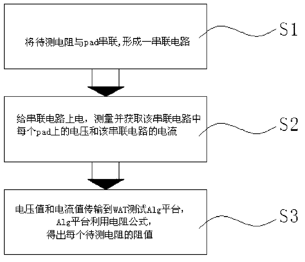
[0029] figure 2 It is a schematic flow chart of the resistance testing method in the embodiment of the present invention:

[0030] S1. Connect N resistors to be tested in series with M pads to form a series circuit, and a resistor to be tested is arranged between two adjacent pads in the series circuit; wherein, M and N are both positive integers, And M=N+1;

[0031] S2. Power on the series circuit, measure the current I in the series circuit, and use a probe card to measure and obtain the voltage value on each pad in the series circuit, wherein the voltage values ​​of two adjacent pads are Um and Um-1, there are multiple metal pins on the bottom of the probe card, the voltage value at the pad can be measured after the metal pins are in contact with the pad. The current is equal, only need t...


PUM


Abstract

The invention relates to the field of micro-electronics testing, in particular to a resistance test method which comprises resistors to be tested and test pads. In the test process, two pads and the resistors to be tested are connected in series through metal wires, a current I is outputted, then voltage of the two pads is tested through using of a probe card, a WAT test Alg platform calculates the absolute value of the difference of the two voltage values, then the absolute value is utilized to be divided by the current, and thus a resistance value of the resistors to be tested can be conveniently obtained. According to the method, traditional resistance test circuits are in series connection, a principle that the current in a series circuit is equal everywhere is used, the current needs to be tested just once, meanwhile the voltage of adjacent pads is tested, resistance values of the resistors to be tested between the adjacent pads can be conveniently figured out according to an algorithm, operating steps are simplified, a great amount of test time is saved, and test cost of enterprises is reduced at the same time.

Description

technical field [0001] The invention relates to the field of microelectronic testing, in particular to a resistance testing method. Background technique [0002] With the continuous advancement of technology in the semiconductor field, in order to ensure the yield rate of the wafer in the production process and keep abreast of the production situation, it is necessary to test the resistance value of the silicon wafer, and pass the detected resistance value through WAT (Wafer Acceptance Test, wafer Round reception test) Alg platform for output and storage, which is convenient for technicians to control the production of silicon wafers to ensure the yield rate of wafers in production. [0003] Chinese patent (application number: 201210273406.8) discloses a method for testing resistance, wherein the method includes the following steps: connecting the four test terminals of the testing machine to the four testing terminals of the resistance to be tested, wherein the testing mach...

Claims


Application Information

Patent Timeline
Patent Type & Authority Applications(China)
IPC IPC(8): G01R27/08
Inventor 沈茜莫保章娄晓祺
Owner SHANGHAI HUALI MICROELECTRONICS CORP
Learn More