
Distribution interference-type optical fiber radiation field safety monitoring system

A safety monitoring system and radiation field technology, applied in signal transmission systems, non-electrical signal transmission systems, instruments, etc., can solve problems such as not going to the market, radiation processing technology stagnation, and inability to fully control the radiation field conditions

Inactive Publication Date: 2013-06-05
天津市技术物理研究所有限公司
View PDF0 Cites 0 Cited by
  • Summary
  • Abstract
  • Description
  • Claims
  • Application Information

AI Technical Summary

Problems solved by technology

[0003] More than 20 years ago, most of my country's radiation processing technology remained in the laboratory and did not go to the market
[0006] At present, the traditional radiation field safety monitoring technology mainly uses camera monitoring, warning lights and alarm bells, and door control interlocking, etc., but these devices can only monitor certain fixed points in the radiation field, and cannot fully control the entire radiation field situation , once people are in other uncovered areas during the production process, it will cause extremely serious consequences

Method used


Image

  • Distribution interference-type optical fiber radiation field safety monitoring system
  • Distribution interference-type optical fiber radiation field safety monitoring system

Examples


Embodiment Construction

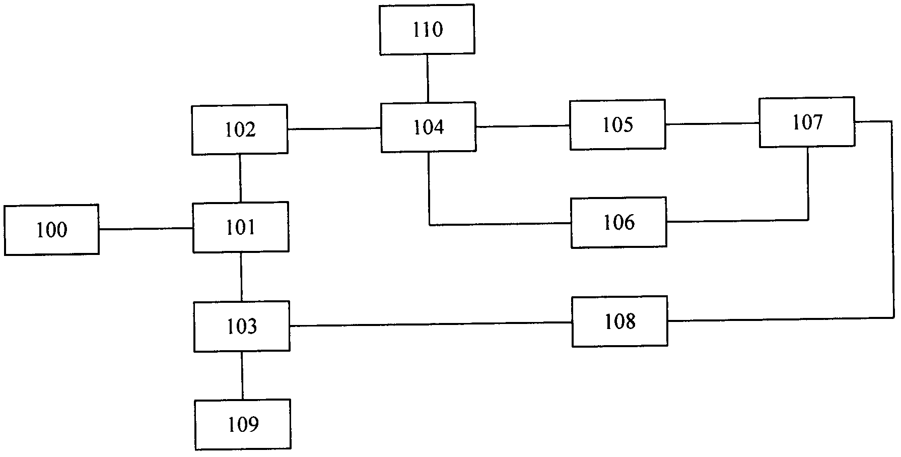
[0017] 1. In normal times, the narrowband laser from [100] is launched in two different directions through [101], one side goes through [102], and enters [105] and [106] through [104], at [107] Coupling, then via [108], [103], and finally into [109] to form an analog signal; the other party via [103], [108], and via [107] to enter [105] and [106], in [ 104], and finally enter [110] to form another analog signal. The two signals are respectively amplified and filtered through [111], [113] and [112], [114], then enter [115] to complete digital signal processing, and finally pass into [116] to obtain a stable soil background Vibration signal spectrum, as the environmental background standard.

[0018] 2. When there are people in the radiation field, because [115] and [116] are pre-laid in the maze channel of the radiation field, the vibration caused by the people will cause changes in the optical transmission parameters in [115] and [116]. As mentioned in 1, there is a time delay ...


PUM


Abstract

The invention relates to a radiation field safety monitoring system based on a distribution interference-type optical fiber sensing technology. According to the radiation field safety monitoring system based on the distribution interference-type optical fiber sensing technology, the monitoring system requires a group of optical cables to be pre-laid inside a radiation field maze, optical fibers in the optical cables are used as a micro vibration sensor, and situations in the radiation field maze are monitored. When personnel enter the maze, vibration existing inside the maze can be monitored in a real-time mode through the optical fiber micro vibration sensor, and the position where the vibration takes place can be rapidly and accurately located. The monitoring system is mainly composed of the distribution interference-type optical fiber micro vibration sensor, a digital signal processing system and a vibration signal analysis system. According to the monitoring technology, wrong-entering conditions of the personnel in the radiation field maze can be monitored, and an alarm can be sent out, and the position where a vibration event takes place is located accurately, and the monitoring technology has extremely high sensitivity and positioning accuracy, and is strong in anti-interference performance.

Description

Technical field [0001] The invention is a safety monitoring system used in radiation fields such as accelerators, cobalt sources, etc., which can realize comprehensive monitoring of personnel in the radiation field area. Involved in the field of radiation safety monitoring. Background technique [0002] Radiation processing is a technology developed in the 1950s, including radiation chemical engineering, radiation materials, radiation disinfection and sterilization, food radiation preservation, and environmental "three wastes" radiation treatment. my country's radiation technology research began in the late 1950s. After years of development and application, radionuclear technology has been widely used in the national economy. [0003] More than 20 years ago, most of my country's radiation processing technology remained in the laboratory and did not go to the market. Since the late 1980s, the application of radiation processing has developed in an all-round way. Relevant units be...

Claims


Application Information

Patent Timeline
IPC IPC(8): G08C23/06
Inventor 唐卫东叶明旸徐涛刘昕孔祥山杨斌
Owner 天津市技术物理研究所有限公司
Learn More