
Parallel inverter device

An inverter and main inverter technology, applied in the direction of converting AC power input to DC power output, output power conversion devices, electrical components, etc., can solve the inverter output voltage error, damage to semiconductor switching elements, etc. problems, to reduce errors, prevent eddy currents, and reduce overall size and weight

Inactive Publication Date: 2013-06-05
FUJI ELECTRIC CO LTD
View PDF5 Cites 7 Cited by
  • Summary
  • Abstract
  • Description
  • Claims
  • Application Information

AI Technical Summary

Problems solved by technology

[0015] However, even in the event of these connection forms, it may happen that not all the inverter voltage command values ​​coincide in time due to the delay in transmitting the control signal, and it may happen that an error occurs between the inverter output voltages Case
In this case, there are problems in that excessive eddy current flows between the power converters through the wiring inductance of the output cables of the power converters connected in parallel, and semiconductor switching elements are damaged, etc.

Method used


Image

  • Parallel inverter device
  • Parallel inverter device
  • Parallel inverter device

Examples


Embodiment Construction

[0028] Hereinafter, a description will be given of one embodiment of the present invention based on the drawings.

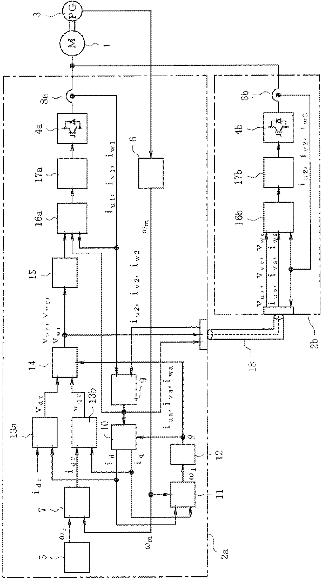
[0029] figure 1 is a block diagram showing the configuration of this embodiment, in which a parallel inverter device is a device for driving one AC motor 1 such as an induction motor by the summed output of two inverters 2a and 2b connected in parallel. Although the inverters 2a and 2b and the AC motor 1 have a three-phase configuration, they consist of figure 1 The one-line diagram in .

[0030] exist figure 1 In , a rotational position detection unit 3 (such as a pulse encoder) for acquiring rotational angle information is connected to the motor 1 . Also, among the inverters 2a and 2b for driving the motor 1, one inverter 2a serves as a master inverter and the other inverter 2b serves as a slave inverter, wherein the master inverter 2a generates and is used for The voltage command value v of the power converter 4a controlling the inverter 2a ur , v vr ...


PUM


Abstract

Inverters connected in parallel each include a power converter that carries out a direct current to alternating current conversion and supplies voltage to a motor, and a control unit, where one of the inverters is a master inverter and the control unit computes a voltage command value for the power converter in the one inverter, while the other inverter is a slave inverter and the power converter in the slave inverter is driven by the voltage command value, a transmission means transmits the voltage command value, and the control unit of the master inverter includes a delay device that delays the voltage command value by a transmission time needed when transmitting a computed voltage command value to the slave inverter, and provides the voltage command value delayed by the delay device to the power converter of the master inverter.

Description

technical field [0001] The present invention relates to a parallel inverter device that drives a load such as an AC motor using a plurality of inverters connected in parallel. Background technique [0002] In general, an inverter is composed of a power converter and a control device that controls the power converter. When the AC motor is driven by the inverter, a torque command value or a voltage command value sent from the control device is transmitted to a plurality of power converters, and the operation of each power converter is performed. [0003] For example, a known technique in which each of a plurality of inverters includes an output current control system and each inverter individually drives an AC motor is described in JP-A-3-159596 (page 3, upper left column, line 8 To line 13 in the lower left column, figure 2 etc.) are described. [0004] Figure 4 In JP-A-3-159596 (page 3, line 8 in the upper left column to line 13 in the lower left column, figure 2 etc.)...

Claims


Application Information

Patent Timeline
Patent Type & Authority Applications(China)
IPC IPC(8): H02M7/493
CPCH02M7/537H02M7/493
Inventor 金子贵之
Owner FUJI ELECTRIC CO LTD
Learn More