Low noise amplifier

A low-noise amplifier, numbering technology, applied to high-frequency amplifiers, improved amplifiers to reduce noise effects, etc., can solve problems such as limited output gain capability

Active Publication Date: 2013-06-05
SHANGHAI HUAHONG GRACE SEMICON MFG CORP
View PDF5 Cites 9 Cited by
  • Summary
  • Abstract
  • Description
  • Claims
  • Application Information

AI Technical Summary

Problems solved by technology

[0002] At present, commonly used low-noise amplifiers designed in RF CMOS technology (such as figure 1 As shown), it is a source feedback type cascode low noise amplifier. Its basic principle is to use the source inductance

Method used


Image

  • Low noise amplifier
  • Low noise amplifier
  • Low noise amplifier

Examples


Embodiment Construction

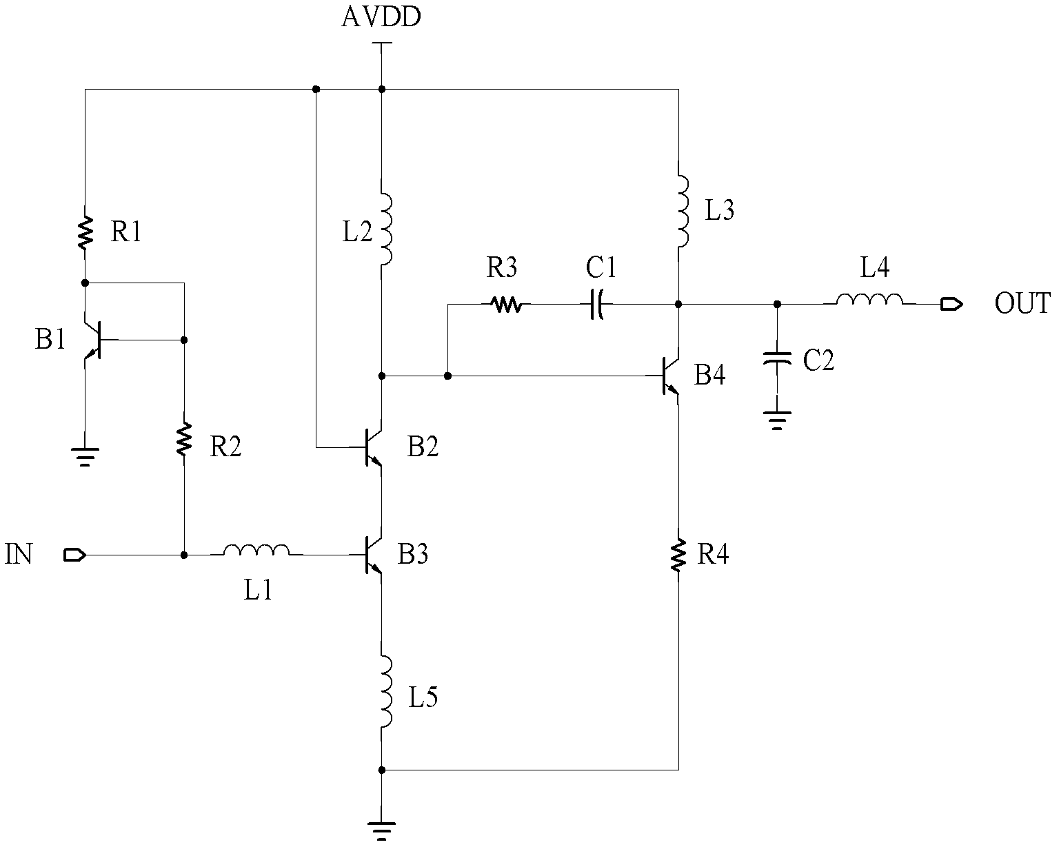
[0025] Such as figure 2 As shown, the low noise amplifier of the present invention includes:

[0026] 4 PMOS tubes, numbered B1 to B4; 4 inductors, numbered L1 to L5; 4 resistors, numbered R1 to R4; 5 inductors, numbered L1 to L5 and 2 capacitors C1, C2;

[0027] The input terminal IN is connected to one end of L1 and R2, the other end of L1 is connected to the gate of B3, and the other end of R2 is connected to the gate of B1; the drain of the gate of B1 is short-circuited, and its source is grounded;

[0028] The power supply voltage AVDD is connected to one end of R1, one end of L2, one end of L3 and the gate of B2, the other end of R1 is connected to the drain of B1, the other end of L2 is connected to the drain of B2 and the gate of B4, and the other end of L3 is connected to the drain of B4;

[0029] One end of R3 is connected to the drain of B2, the other end is connected to the positive pole of C1, one end of the negative pole of C1 is L4, the other end of L4 is conn...


PUM


Abstract

The invention discloses a low noise amplifier which comprises four p-channel metal oxide semiconductor (PMOS) tubes, five inductors, four resistors, two capacitors. The four PMOS tubes comprise a PMOS tube B1, a PMOS tube B2, a PMOS tube B3 and a PMOS tube B4. The five inductors comprise an inductor L1, an inductor L2, an inductor L3, an inductor L4 and an inductor L5. The four resistors comprise a resistor R1, a resistor R2, a resistor R3 and a resistor R4. The two capacitors comprise a capacitor C1 and a capacitor C2. An input end is connected with one end of the L1 and one end of the R2, the other end of the L1 is connected with a grid electrode of the B3, and the other end of the R2 is connected with a grid electrode of the B1. The grid electrode and a drain electrode of the B1 are connected in a short circuit mode, and a source electrode of the B1 is in ground connection. Supply voltage is connected with one end of the R1, one end of L2, one end of the L3 and a grid electrode of the B2, the other end of the R1 is connected with the drain electrode of the B1, the other end of the L2 is connected with a drain electrode of the B2 and a grid electrode of the B4, and the other end of the L3 is connected with a drain electrode of the B4. One end of the R3 is connected with the drain electrode of the B2, the other end of the R3 is connected with a positive electrode of the C1, a negative electrode of the C1 is connected with one end of the L4, and the other end of the L4 is connected with an output end. A positive electrode of the C2 is connected with the drain electrode of the B4, and a negative electrode of the C2 is in ground connection. A source electrode of the B2 is connected with a drain electrode of the B3, a source electrode of the B3 is in ground connection through the L5, and a source electrode of the B4 is in ground connection through the R4. The low noise amplifier can achieve gains more than 30db, and can obtain a noise index below 1.5db at the same time.

Description

technical field [0001] The invention relates to the field of integrated circuits, in particular to a low noise amplifier. Background technique [0002] At present, commonly used low-noise amplifiers designed in RF CMOS technology (such as figure 1 As shown), it is a source feedback type cascode low noise amplifier. Its basic principle is to use the source inductance Ls to resonate with the gate capacitance Cgs of the MOS transistor, so as to obtain a real impedance to achieve the matching of the input impedance. Now The downside of having an LNA is its limited output gain capability. Contents of the invention [0003] The technical problem to be solved by the present invention is to provide a low-noise amplifier capable of achieving a gain of more than 30dB and at the same time obtaining a noise index of less than 1.5dB. [0004] In order to solve the problems of the technologies described above, the low noise amplifier of the present invention includes: [0005] 4 PMOS...

Claims


Application Information

Patent Timeline
IPC IPC(8): H03F1/26H03F3/189
Inventor 朱红卫刘国军胡冠斌
Owner SHANGHAI HUAHONG GRACE SEMICON MFG CORP
Why Eureka
Try Eureka