Check patentability & draft patents in minutes with Patsnap Eureka AI!

Peripheral equipment and parallel bus system

一种周边设备、总线系统的技术,应用在仪器、电数字数据处理等方向,能够解决无法识别周边设备连接在哪一个安装位置上等问题,达到确保布线损失的效果

Inactive Publication Date: 2013-06-05
MITSUBISHI ELECTRIC CORP
View PDF7 Cites 2 Cited by
  • Summary
  • Abstract
  • Description
  • Claims
  • Application Information

AI Technical Summary

Problems solved by technology

[0006] However, when peripheral devices of the same specification are connected to the parallel bus system, since the installation conditions of each peripheral device to the control device are completely equal electrically, it is impossible to identify which installation position each peripheral device is connected to from the control device side.

Method used


Image

  • Peripheral equipment and parallel bus system
  • Peripheral equipment and parallel bus system
  • Peripheral equipment and parallel bus system

Examples


Embodiment approach 1

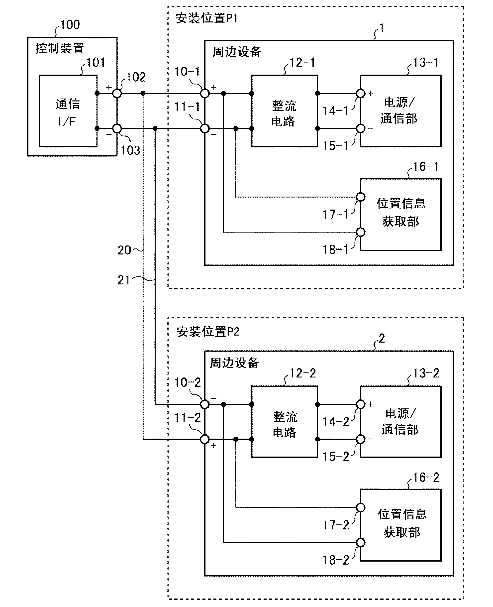
[0040] Such as figure 1 As shown in the example, the parallel bus system according to Embodiment 1 includes: a control device 100, a peripheral device 1 installed at an installation position P1, a peripheral device 2 installed at an installation position P2, and buses 20, 21 . For example, when implementing the airbag activation system of a vehicle using this parallel bus system, an ECU (Electronic Control Unit: Electronic Control Unit) is used as the control device 100, and accelerations installed at predetermined installation positions P1 and P2 of the vehicle are used. Sensors as peripherals 1,2. In addition, in the case of implementing an obstacle detection system for a vehicle, the ECU is used as the control device 100 and the ultrasonic sensors installed at predetermined installation positions P1 and P2 of the vehicle are used as the peripheral devices 1 and 2 in the same manner. Of course, Embodiment 1 can be applied to any system in which the control device and peri...

Embodiment approach 2

[0077] Figure 15 It is a block diagram showing the configuration of the parallel bus system according to Embodiment 2 of the present invention. exist Figure 15 in, for with figure 1 The same or corresponding parts are marked with the same reference numerals, and descriptions are omitted.

[0078] Such as Figure 15 As shown, the parallel bus system involved in Embodiment 2 includes: a control device 100, a peripheral device 1 installed at an installation position P1, a peripheral device 2 installed at an installation position P2, and a bus 20. Among the bus 20 A voltage drop element such as a resistor 40 is connected to the line branching to the peripheral device 2 .

[0079] The connector terminal 102 of the control device 100 is connected to the bus 20 , and the connector terminal 103 is grounded.

[0080] The connector terminal 10-1 of the peripheral device 1 is connected to the bus 20, and the connector terminal 11-1 is grounded. Similarly, in another peripheral d...


PUM


Abstract

The invention provides peripheral equipment and a parallel bus system. The polarities of bus lines (20, 21) are switched in accordance with attachment locations and connection is made to peripheral equipment (1, 2). Location information acquisition units (16-1, 16-2) determine the attachment location as being attachment location (P1) if the polarities of connector terminal (10-1) (or (10-2)) and connector terminal (11-1) (or (11-2)) are plus-minus and determine the attachment location as being attachment location (P2) if said polarities are minus-plus.

Description

technical field [0001] The present invention relates to a peripheral device connected to a control device using a parallel bus, and a parallel bus system connecting a control device to a plurality of peripheral devices. Background technique [0002] In the case of a bus connection of peripherals to the control unit, there is Figure 19 (a) A serial bus system in which the peripheral devices 1 and 2 are serially connected to the control device 100 as shown (for example, refer to Patent Document 1), and Figure 19 As shown in (b), a parallel bus system in which the wiring is branched to connect the respective peripheral devices 1 and 2 (for example, refer to Patent Document 2). here, Figure 19 (a), Figure 19 (b) both exemplify the case of two buses. [0003] exist Figure 19 (a) In the serial bus system shown as an example, the peripheral device 1 is connected to the control device 100, and the peripheral device 2 is connected to the peripheral device 1 to connect them in se...

Claims


Application Information

Patent Timeline
Patent Type & Authority Applications(China)
IPC IPC(8): G06F13/14
CPCG06F13/4204G06F13/14
Inventor 山下利幸平冈裕二
Owner MITSUBISHI ELECTRIC CORP
Features
  • R&D
  • Intellectual Property
  • Life Sciences
  • Materials
  • Tech Scout
  • Unparalleled Data Quality
  • Higher Quality Content
  • 60% Fewer Hallucinations
Learn More