
Full-automatic assembly machine for clamping spring

An assembly machine and fully automatic technology, applied in metal processing, metal processing equipment, manufacturing tools, etc., can solve problems such as high labor intensity, scratches on the supercharger casing, hidden safety hazards, etc., to improve work efficiency and yield , Put an end to personnel safety hazards, the effect of high degree of automation

Inactive Publication Date: 2013-06-12
吴康伟
View PDF6 Cites 22 Cited by
  • Summary
  • Abstract
  • Description
  • Claims
  • Application Information

AI Technical Summary

Problems solved by technology

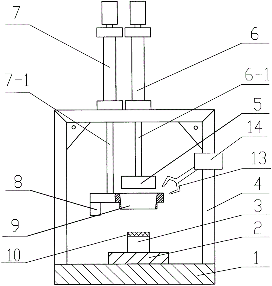
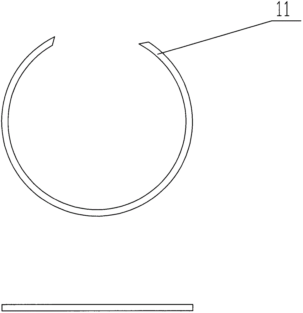
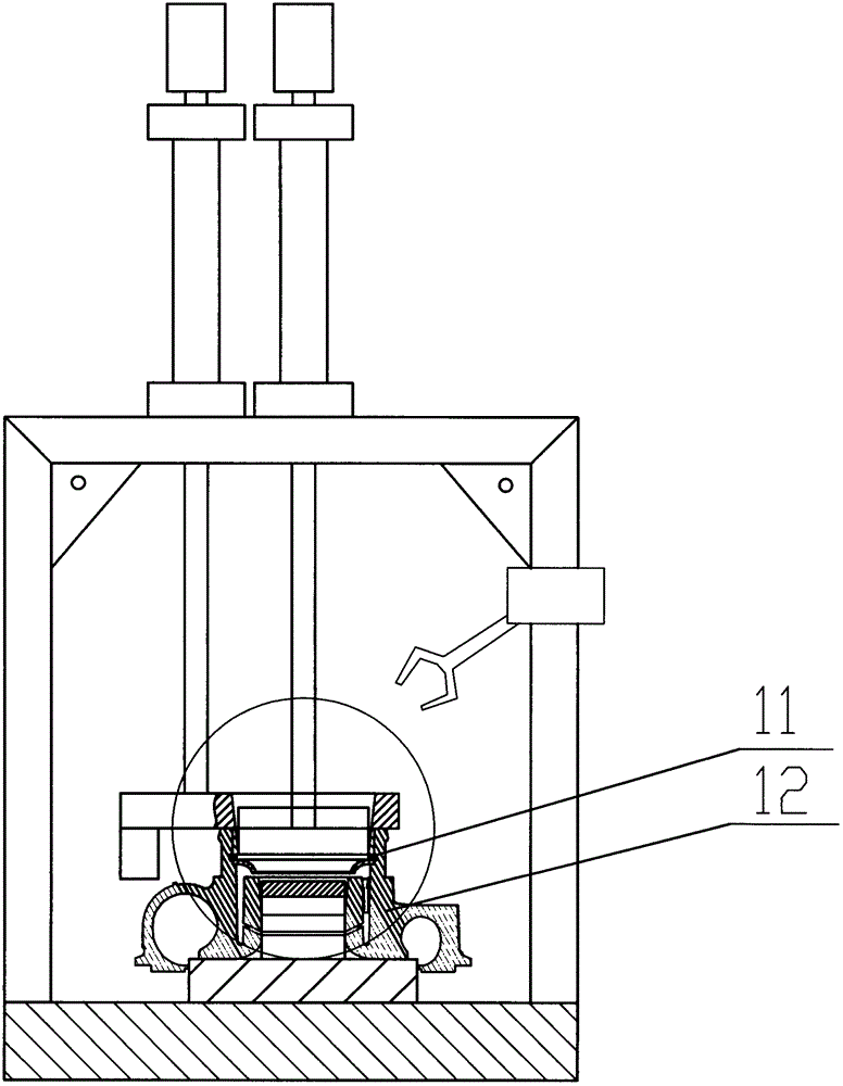
[0002] At present, during the assembly process of the supercharger casing, a kind of circlip needs to be installed in the circlip groove of the air inlet of the supercharger casing. Make it smaller and then press it into the retaining ring groove of the air inlet of the supercharger casing. The disadvantage of this method is that it is labor-intensive, and often the clamping is not in place, and it cannot be attached to the retaining spring groove of the air inlet of the supercharger casing. It will seriously affect the consistency and performance of the supercharger casing assembly, leading to the failure of the supercharger muffler, and it is easy to cause scratches, burrs, etc. in the inner hole of the supercharger casing and be scrapped, resulting in a low pass rate. In addition, this method has the risk of scratching hands and has certain safety hazards

Method used


Image

  • Full-automatic assembly machine for clamping spring
  • Full-automatic assembly machine for clamping spring
  • Full-automatic assembly machine for clamping spring

Examples


Embodiment Construction

[0012] The present invention will be further described below in conjunction with the accompanying drawings and specific embodiments.

[0013] figure 1 It is a structural schematic diagram of a preferred embodiment of a fully automatic circlip assembly machine, which is used to assemble the circlip into the circlip slot of the air inlet of the supercharger casing, which includes a workbench 1, a cylinder 6, a cylinder 7, a manipulator 14 and Bracket 4, both sides of the bracket 4 are right-angled brackets, the tops of the two right-angled sides are fixedly connected to the table top of the workbench 1, the middle right-angled side is parallel to the table top of the workbench 1, and the right-angled side is fixedly connected with the cylinder 6 And the cylinder 7, the piston rod 6-1 on the cylinder 6 faces the table top of the workbench, and the bottom of the piston 6-1 is fixedly connected with the final shaft 5. The bottom of the lower end of the piston rod 7-1 of the cylind...


PUM


Abstract

The invention relates to an assembly machine, in particular to a full-automatic assembly machine for a clamping spring and a clamping spring groove of an air inlet of a supercharger housing. The full-automatic assembly machine for the clamping spring comprises a working platform, two air cylinders, a manipulator and a bracket, wherein the air cylinders are supported above the working platform through the bracket; a piston rod of one air cylinder is arranged over against a platform surface of the working platform; the bottom of the lower end of the piston rod is fixedly connected with a pressing shaft; the bottom of the lower end of a piston rod of the other air cylinder is fixedly connected with a guide sleeve; a base is arranged on the platform surface of the working platform; a positioning circle is arranged on the base; and after a workpiece is clamped and fixed, the manipulator is used for feeding. The full-automatic assembly machine has the advantages that the assembly machine adopts pneumatic power, and adopts the manipulator for the feeding; the automation degree is high; manual operation is not required; a labor force is saved; the work efficiency is improved greatly; a finished product rate is increased greatly; waste products are reduced; and potential safety hazards of staff are avoided.

Description

technical field [0001] The invention relates to a pneumatic assembling machine, in particular to a fully automatic assembling machine for a ring groove and a ring at the air inlet of a supercharger casing. Background technique [0002] At present, during the assembly process of the supercharger casing, a kind of circlip needs to be installed in the circlip groove of the air inlet of the supercharger casing. Make it smaller and then press it into the retaining ring groove of the air inlet of the supercharger casing. The disadvantage of this method is that it is labor-intensive, and often the clamping is not in place, and it cannot be attached to the retaining spring groove of the air inlet of the supercharger casing. It will seriously affect the consistency and performance of the supercharger casing assembly, leading to the failure of the supercharger muffler, and it is easy to cause scratches, burrs, etc. in the inner hole of the supercharger casing and be scrapped, resultin...

Claims


Application Information

Patent Timeline
IPC IPC(8): B23P19/027
Inventor 吴康伟
Owner 吴康伟
Learn More