Edge precision control method of large aperture optical element being processed through air bag polishing

A technology of airbag polishing and optical components, which is applied in metal processing equipment, optical surface grinders, grinding/polishing equipment, etc., can solve the problems of destroying the accuracy of the main surface, high risk, and high cost, so as to improve processing efficiency, simple operation, Effect of Accuracy Improvement

Active Publication Date: 2013-06-12
HARBIN INST OF TECH
View PDF3 Cites 17 Cited by
  • Summary
  • Abstract
  • Description
  • Claims
  • Application Information

AI Technical Summary

Problems solved by technology

[0003] The present invention aims to solve the problems of destroying the main surface accuracy, high risk, high cost and low efficiency caused by the "edge effect" process of the existing optical element processing method, thereby providing an edge accuracy for large-diameter optical elements in the airbag polishing process. Control Method

Method used


Image

  • Edge precision control method of large aperture optical element being processed through air bag polishing
  • Edge precision control method of large aperture optical element being processed through air bag polishing
  • Edge precision control method of large aperture optical element being processed through air bag polishing

Examples


specific Embodiment approach 1

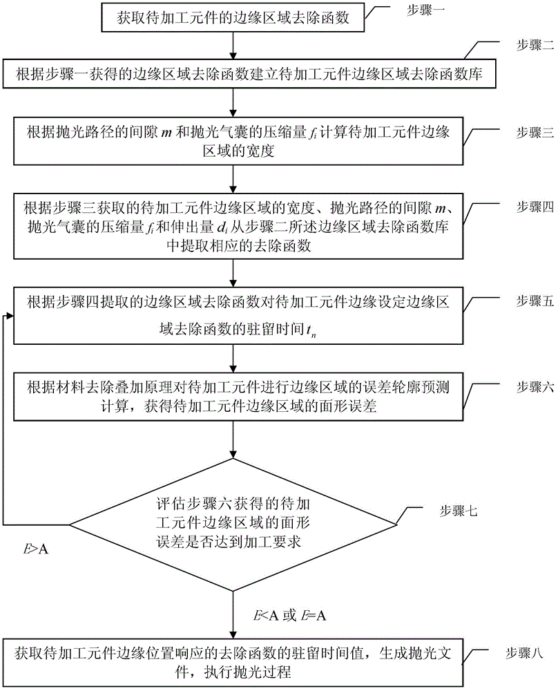
[0035] Specific implementation mode 1. Combination Figure 1-3 This specific embodiment will be described. The method for controlling the edge accuracy of large-diameter optical elements in airbag polishing process comprises the following steps:

[0036] Step 1: Obtain the edge area removal function of the material corresponding to the component to be processed;

[0037] Step 2: Establish the edge area removal function library of the component to be processed according to the edge area removal function obtained in step 1. The edge area removal function library is based on the compression amount f of the polishing airbag i and overhang d i One-to-one corresponding edge area removal function;

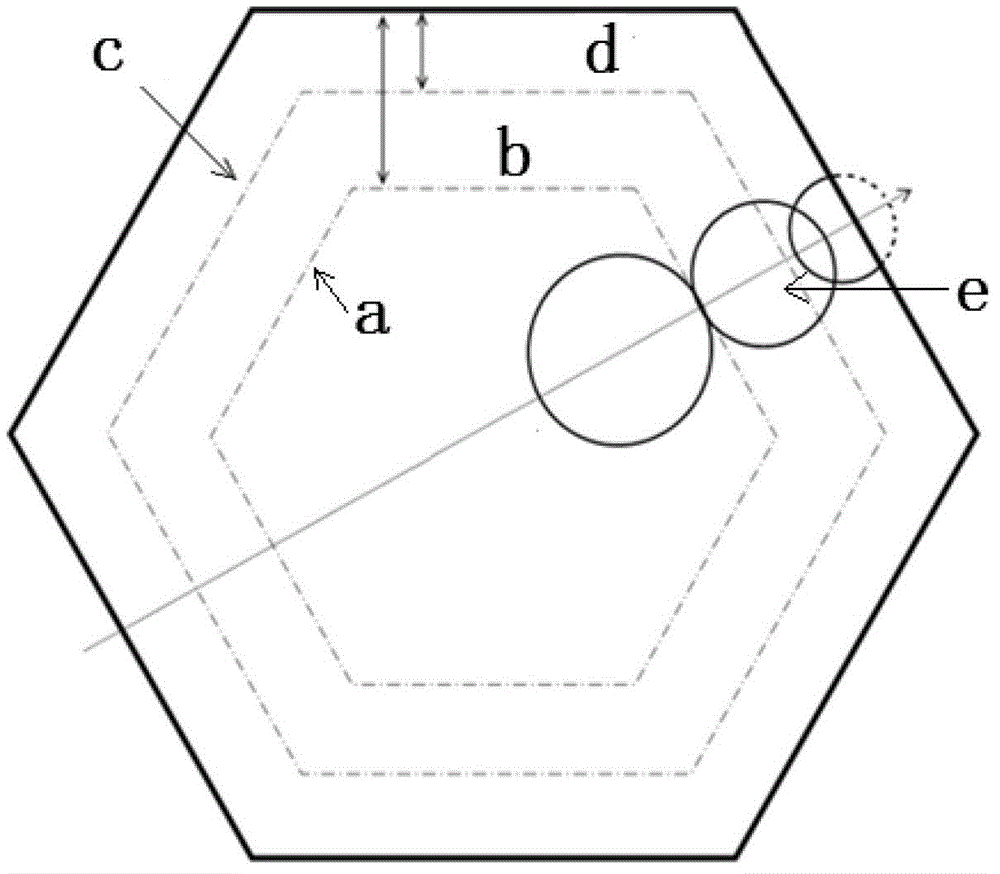
[0038] Step 3: According to the gap m of the polishing path and the compression amount f of the polishing air bag i Calculate the width of the edge area of ​​the component to be processed;

[0039] Step 4: According to the width of the edge area of ​​the component to be processed obt...

specific Embodiment approach 2

[0052] Embodiment 2. The difference between this embodiment and Embodiment 1 is that the process of setting the dwell time of the edge region removal function for the edge of the component to be processed according to the corresponding edge region removal function extracted in step 4 in step 5 is as follows , where the error distribution in the marginal region during this process is e 0 (x,y) edge , the root mean square value of the error distribution in the marginal area is E 0 :

[0053] Step 5A: Set the residence time t for n edge area removal functions on the edge area of ​​the component to be processed n , i=1, 2...n;

[0054] Step 5B: Calculate the error distribution e of the edge region at the dwell time in Step 5A 0 (x,y) edge ;

[0055] e 0 ( x , y ) edge = Σ i ...

specific Embodiment approach 3

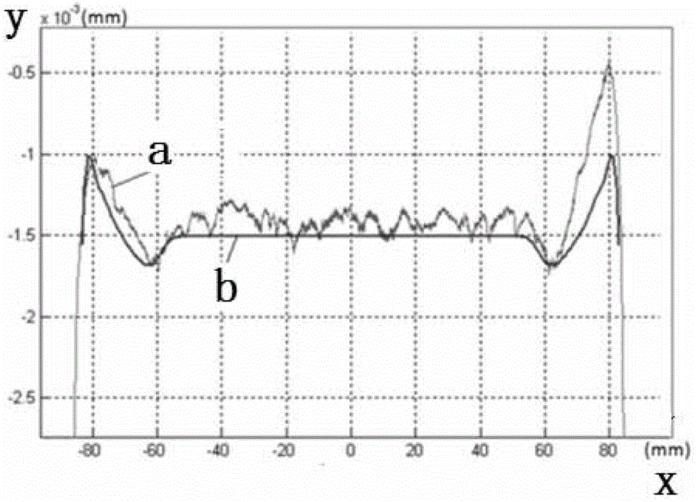
[0061] Specific Embodiment 3. The difference between this specific embodiment and specific embodiment 1 is that in the step 6, the error contour prediction calculation of the edge area of ​​the element to be processed is performed according to the principle of material removal and superposition, and the surface shape error of the edge area of ​​the element to be processed is obtained. Root mean square value E, its process is:

[0062] Step 6A: The gap m of the polishing path, the edge area of ​​the component to be processed has n edge area removal functions where i=1, 2...n; f i Compression of polished airbag, d i is the amount of protrusion; then the error distribution e(x, y) of the edge area of ​​the component to be processed edge Calculated by the following formula:

[0063] e ( x , y ) edge = Σ i ...


PUM


Abstract

The invention discloses an edge precision control method of a large aperture optical element being processed through air bag polishing, and relates to a method for controlling edge precision in an air bag polishing element processing process, belonging to the field of optical processing. With the adoption of the edge precision control method, the problems that in the existing optical element processing process, in order to overcome 'edge effect', the risk of damaging main face precision is high, the cost is high, and the efficiency is low are solved. The method comprises the following steps: acquiring an edge area removing function of materials corresponding to the element to be processed; establishing an edge area removing function library of the element to be processed; calculating the width of an edge area of the element to be processed according to gap m of a polishing path and compression amount fi of a polishing air bag; extracting the corresponding removing function; setting residence time tn of the edge area removing function; carrying out error contour predication calculation on the edge area of the element to be processed, so as to acquire surface-shape error of the edge area of the element to be processed; estimating the surface-shape error; and acquiring a residence time value of the removing function responding to the edge position of the element to be processed, so as to generate a polishing file ,and executing a polishing process. The edge precision control method provided by the invention can be widely applied in the edge precision control processing process of large aperture opt elements.

Description

technical field [0001] The invention relates to a method for controlling edge precision during the processing of airbag polishing components, belonging to the field of optical processing. Background technique [0002] The processing of the edge area of ​​the mirror surface is a difficult point in the processing of large-aperture optical components. Traditional optical processing technology and computer-controlled small-size tool processing technology have no good solutions for this. This is because the non-continuous local action of the polishing tool on the edge of the component to be processed leads to a sharp drop in the accuracy of the edge area of ​​the component to be processed. If the polishing tool does not protrude from the edge of the component to be processed, warping will occur in the edge area, and if it protrudes from the edge of the component to be processed, it is prone to "sag". Once the "sagging edge" occurs, the entire processing process will start from s...

Claims


Application Information

Patent Timeline
Patent Type & Authority Applications(China)
IPC IPC(8): B24B13/00B24B51/00
Inventor 李洪玉汪洪源张伟
Owner HARBIN INST OF TECH
Why Eureka
Try Eureka