Control method, equipment, system and construction machinery for multi-joint mechanical arm support

A robotic arm, multi-joint technology, applied in mechanically driven excavators/dredgers, mining equipment, cranes, etc., can solve the problems that the end of the multi-joint boom cannot be accurately reached and the operation efficiency is low.

Active Publication Date: 2013-06-12
ZOOMLION HEAVY IND CO LTD
View PDF4 Cites 48 Cited by
  • Summary
  • Abstract
  • Description
  • Claims
  • Application Information

AI Technical Summary

Problems solved by technology

[0011] The embodiment of the present invention provides a control method, equipment, system and construction machinery of a multi-joint mechanical arm, which is used to solve the ina

Method used


Image

  • Control method, equipment, system and construction machinery for multi-joint mechanical arm support
  • Control method, equipment, system and construction machinery for multi-joint mechanical arm support
  • Control method, equipment, system and construction machinery for multi-joint mechanical arm support

Examples


Embodiment 1

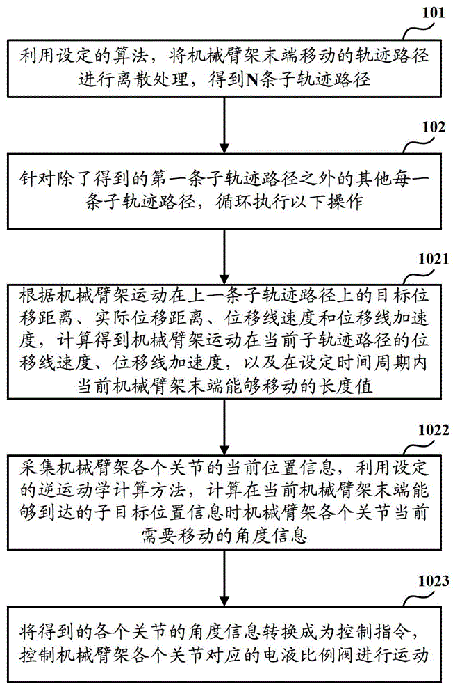
[0041] Such as figure 2 As shown, it is a flowchart of a control method of a multi-joint mechanical arm frame according to Embodiment 1 of the present invention, and the method includes:

[0042] Step 101: Divide the trajectory path of the end movement of the mechanical arm frame into N sub-trajectory paths by using the set method of simulating the end movement of the mechanical arm frame.

[0043] Wherein, N is a positive integer not less than 1.

[0044] In step 101, before the discrete operation is performed on the trajectory path of the movement of the end of the mechanical arm, the method further includes: determining the movement trajectory of the end of the mechanical arm.

[0045] Specifically, the method for determining the moving trajectory path of the end of the mechanical arm includes but is not limited to: determining according to the current position information of the end of the mechanical arm and the target position to which it moves.

[0046] After the trajec...

Embodiment 2

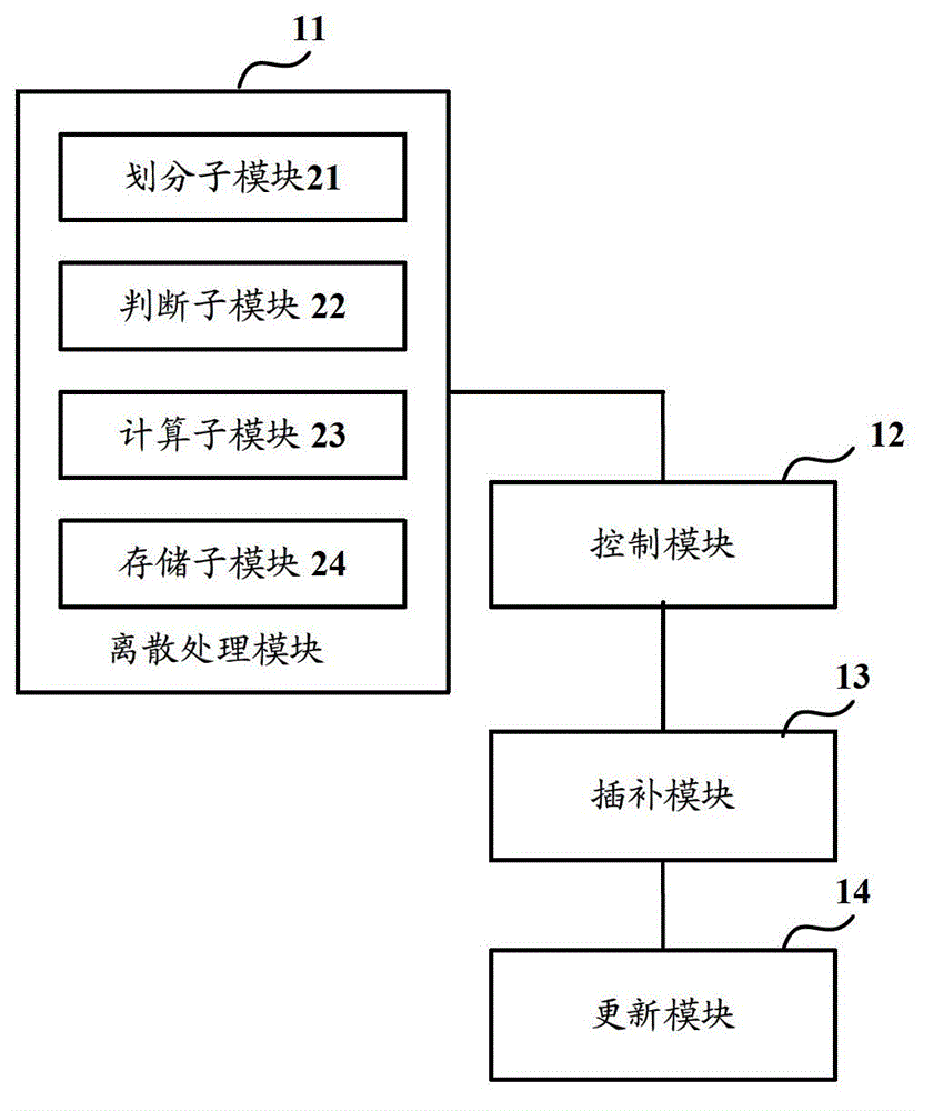
[0101] Such as image 3 As shown, it is a schematic structural diagram of a control device of a multi-joint mechanical arm frame according to Embodiment 2 of the present invention, the device includes: a discrete processing module 11 and a control module 12, wherein:

[0102] The discrete processing module 11 is used to divide the trajectory path of the end movement of the mechanical arm frame into N sub-trajectory paths by using the set method of simulating the end movement of the mechanical arm frame, where N is a positive integer not less than 1;

[0103] The control module 12 is configured to perform the following operations on each sub-track path except the obtained first sub-track path:

[0104] Calculate the displacement linear velocity, displacement linear acceleration and The length value that the end of the current robotic arm can move within the set time period;

[0105] Collect the current position information of each joint of the mechanical arm frame, and use th...

Embodiment 3

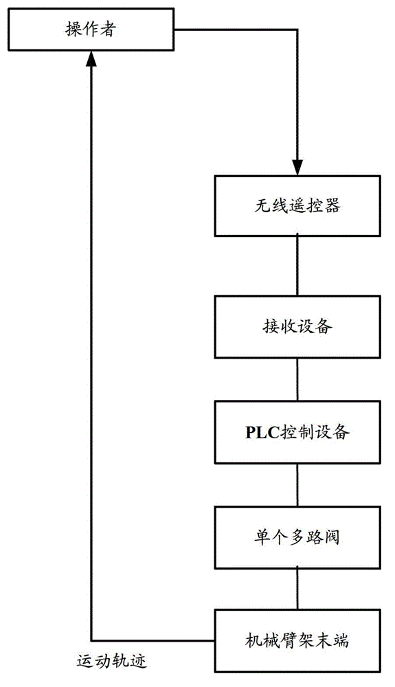
[0130] Such as Figure 4 As shown, it is a schematic structural diagram of a control system of a multi-joint mechanical arm frame according to Embodiment 3 of the present invention. The system includes: acquisition equipment 31, control equipment 32 and electro-hydraulic proportional valve 33, wherein:

[0131] The collecting device 31 is used to collect the current position information of each joint of the mechanical arm frame.

[0132] The control device 32 is used to divide the trajectory path of the end movement of the mechanical arm frame into N sub-trajectory paths by using the set method of simulating the end movement of the mechanical arm frame, where N is a positive integer not less than 1;

[0133] For each sub-trajectory path except the obtained first sub-trajectory path, the following operations are performed respectively: the target displacement distance, actual displacement distance, displacement linear velocity and Displacement linear acceleration, calculate th...


PUM


Abstract

The invention discloses a control method, equipment, a system, and construction machinery for a multi-joint mechanical arm support. The control method mainly comprises the steps that a moving track path of the tail end of the mechanical arm support is divided into a plurality of sub track paths; aiming at each sub track path, the length value that the tail end of the mechanical arm support can move within a set duration, and current position information of each joint of the mechanical arm support is collected to calculate the required moving angle information of each joint of the mechanical arm support under the position information of subgoals capable of being reached by the tail end of the mechanical arm support; the obtained angle information of each joint in converted into control instructions, so that each joint of the mechanical arm support is controlled to move; the track path of the tail end of the mechanical arm support is subjected to discrete programming; and aiming at the sub track paths after programming, the moving angle information of each other joint of the mechanical arm support are determined according to the inverse kinematic principle. Therefore, the operation stability of the tail end of the arm support is guaranteed sufficiently, and the control precision for the tail end of the multi-joint mechanical arm support is improved.

Description

technical field [0001] The invention relates to the field of construction machinery, in particular to a control method, equipment, system and construction machinery of a multi-joint mechanical arm frame. Background technique [0002] Among existing construction machinery products, such as concrete pump trucks, concrete sprayers, truck cranes and hydraulic excavators, the main working devices of large machinery are multi-joint hydraulic mechanical arms. This type of hydraulic manipulator system has the characteristics of many degrees of freedom, large mass, large flexibility, and large inertia. It has the characteristics of high operation complexity and high safety requirements during use, and it works in a complex engineering construction environment for a long time. Therefore, when controlling the multi-joint hydraulic mechanical arm frame of this type of large-scale machinery, the operator's coordination, accuracy and control stability are required to be high. [0003] At...

Claims


Application Information

Patent Timeline
IPC IPC(8): E04G21/02E21D11/10B66C23/70E02F3/38
Inventor 胡敏梁聪慧齐彪曾扬
Owner ZOOMLION HEAVY IND CO LTD
Why Eureka
Try Eureka