
Multifunctional rotary drilling rig

A rotary drilling rig, multi-functional technology, applied in the direction of drilling tools, drilling equipment, earth drilling and mining, etc., can solve the problems of single construction, high cost of rotary drilling rig, failure to realize CFG drilling rig construction, soil squeezing pile machine construction, etc. , to achieve the effect of saving purchase cost and improving work efficiency

Inactive Publication Date: 2013-06-12
山东鑫国重机科技有限公司
View PDF7 Cites 5 Cited by
  • Summary
  • Abstract
  • Description
  • Claims
  • Application Information

AI Technical Summary

Problems solved by technology

However, due to the shallow depth of pile foundations in some grouting projects, such as the high cost of using rotary drilling rigs, the traditional low-cost CFG drilling rig construction or soil-squeezing grouting pile machine construction has an irreplaceable role
In view of the single construction characteristics of the traditional rotary drilling rig above, if a multifunctional rotary drilling rig is designed, it can not only carry out rotary drilling to form holes, but also can be equipped with hanging long auger drilling tools for CFA construction, and can also be equipped with hanging drilling tools for squeezing soil. Realize the function of screw pressure squeezing soil pouring, you can realize one machine with multiple functions, saving the purchase cost
[0003] At present, although there are also multi-functional rotary drilling rigs put into use, such as the multi-functional rotary drilling rig mentioned in the patent No. CN200710191829.4, it is only a simple development of the crane to realize the function of the rotary drilling rig, but fails to realize the CFG Drilling rig construction or earth-squeezing grouting pile machine construction

Method used


Image

  • Multifunctional rotary drilling rig
  • Multifunctional rotary drilling rig
  • Multifunctional rotary drilling rig

Examples


Embodiment Construction

[0025] Embodiments of the present invention are further described below in conjunction with accompanying drawings:

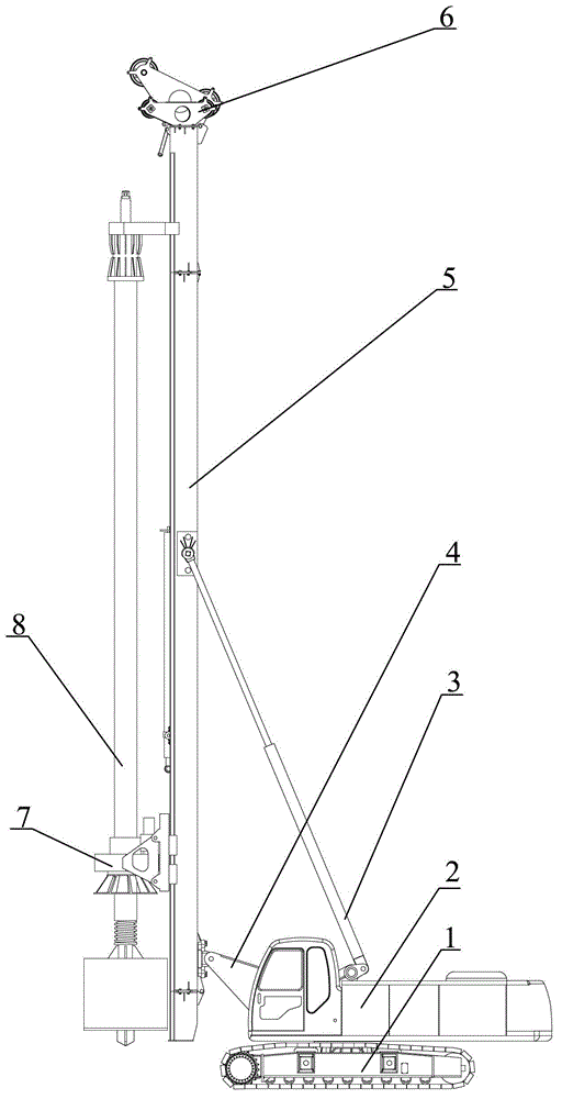
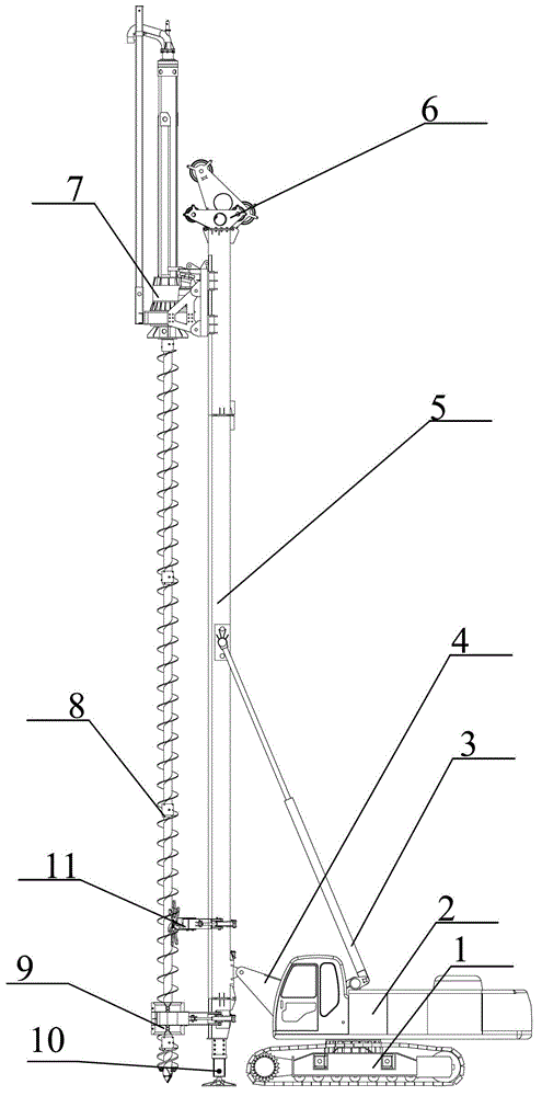
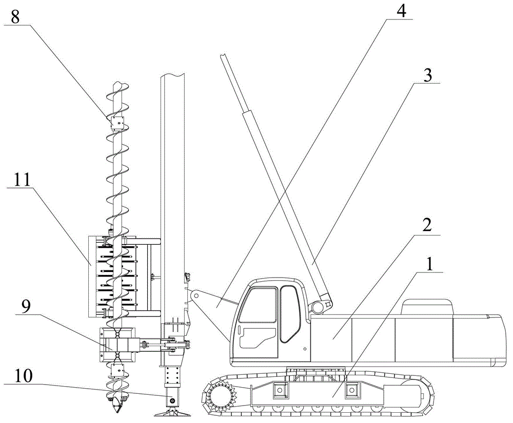
[0026] Such as Figure 1-3 The multifunctional rotary drilling rig shown includes a chassis 1, an upper car 2 installed on the chassis 1, a diagonal bracing cylinder 3 installed on the upper car 2, and a mast 5 connected to the hoisting box 4 and the oblique Support oil cylinder 3, hoist box body 4 is fixed on the front end of boarding car 2, and the end of mast 5 is equipped with straightening device 9, and the top of straightening device 9 is provided with soil clearer 11, and soil clearer 11 is also arranged on mast 5. Legs 10 are installed at the bottom of the mast 5 . The head pulley frame 6 with adjustable orientation is installed on the mast 5 top, and the head pulley frame 6 connects the power head 7. The power head 7 has two hanging positions, and the drilling tool 8 is hung below the hanging positions. Drilling tool 8 is common drilling rod of rotar...


PUM


Abstract

The invention relates to a multifunctional rotary drilling rig and belongs to the field of foundation engineering construction equipment. The multifunctional rotary drilling rig comprises a chassis, an upper wagon mounted on the chassis, a diagonal bracing oil cylinder mounted on the upper wagon and a mast, wherein the mast is connected with a winch box and the diagonal bracing oil cylinder; the winch box is fixed at the front end of the upper wagon; a guide device is mounted at the tail end of the mast; and a soil remover is arranged above the guide device and also arranged on the mast. The multifunctional rotary drilling rig integrates functions of a rotary drilling rig, a CFG (Cement Flyash Gravel Pile) drilling rig and a screw pressure soil squeezing and filling pile drilling rig, and realizes multiple functions and construction by multiple construction methods; the cost for purchasing the drilling rig is saved; and the working efficiency is improved.

Description

technical field [0001] The invention relates to a multifunctional rotary drilling rig, which belongs to the field of foundation engineering construction equipment. Background technique [0002] Due to the domestic turntable rotation and impact reverse circulation pile foundation construction drilling rig, there are disadvantages such as low efficiency, cumbersome transfer of hole positions, great environmental pollution, and high drilling cost. Due to its mechanization, high degree of automation, flexible and convenient on-site displacement, high hole forming efficiency, high axial pressure, high construction efficiency, and environmental protection, the rotary drilling rig is suitable for the geological conditions in most parts of our country with different drilling tools. It is the most ideal construction machine suitable for hole forming in construction pile foundation engineering. However, due to the shallow depth of pile foundations in some grouting projects, such as t...

Claims


Application Information

Patent Timeline
IPC IPC(8): E21B7/02E21B12/06E21B15/00E02D5/36
Inventor 王庆军于克永高海霄王克旭李良
Owner 山东鑫国重机科技有限公司
Learn More