
Calibration device of pull-press integrated sensor

A calibration device and sensor technology, which is applied in the direction of measuring devices, instruments, force/torque/power measuring instrument calibration/testing, etc., can solve the problems of loading position, large loading method, unsatisfactory, large equipment volume, etc., and achieve improvement Calibration efficiency, accurate loading force, and high calibration accuracy

Inactive Publication Date: 2013-06-12
HENAN UNIV OF SCI & TECH
View PDF8 Cites 21 Cited by
  • Summary
  • Abstract
  • Description
  • Claims
  • Application Information

AI Technical Summary

Problems solved by technology

[0005] Existing calibration of tension and pressure sensors generally uses professional equipment such as benchmark dynamometers and piston pressure gauges. These equipment not only have high maintenance costs, but usually only one of the tension or pressure sensors can be calibrated, and the volume of the equipment Large, there are certain requirements for the space of the use environment, which cannot meet the requirements of on-site calibration for most measurement conditions; there are also some relatively simple tension and pressure calibration equipment such as force measuring weights, which can only calibrate tension Or one of the pressure sensors, and this kind of equipment is greatly affected by human influence (loading position, loading method, etc.), and it is difficult to meet the requirements of on-site calibration of tension and pressure sensors

Method used


Image

  • Calibration device of pull-press integrated sensor

Examples


Embodiment Construction

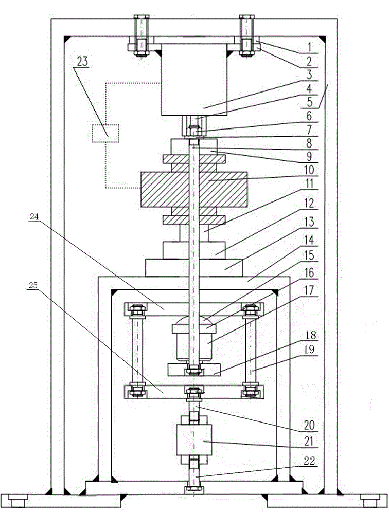
[0020] Examples of the present invention are figure 1 As shown, the specific implementation of this embodiment will be described in detail below in conjunction with the accompanying drawings:

[0021] Tension-compression integrated sensor calibration device, including frame structure 5, the bottom plate of the frame can be fixedly installed on any bottom plate, the top of the frame is equipped with a loading mechanism, the loading mechanism includes a servo motor 3, and the servo motor 3 is welded on the motor bottom plate 2 and fixed on the top beam of the frame by fixing screws and motor fixing gaskets 1, the output shaft 4 of the servo motor 3 is connected with an actuator, the actuator is a nut screw mechanism, and the nut screw mechanism includes a loading nut 6. The nut 6 is connected to the output shaft of the servo motor through a key fit with the inner hexagonal sleeve connected to the output shaft of the servo motor. The inner hexagonal sleeve drives the loading nut ...


PUM


Abstract

The invention relates to a calibration device of a pull-press integrated sensor. The calibration device of the pull-press integrated sensor comprises a rack, wherein a loading mechanism is assembled on the top of the rack. The loading mechanism comprises a driving device and an executing mechanism, wherein the executing mechanism is connected with the driving device and used for outputting up-and-down straight line motion. The executing mechanism comprises a dowel bar, wherein the dowel bar is arranged at the tail end of the executing mechanism, a standard pressure sensor is arranged on the dowel bar, a base seat which is used for supporting and holding a to-be-demarcated pressure sensor is assembled at the tail end of the dowel bar. A baffle is arranged on the upper portion of the base seat. The baffle is assembled on the dowel bar of the executing mechanism anti-dropping in a dipping-and-heaving mode. A first connector which is used for being connected with one end of a to-be-demarcated tension sensor is fixedly connected on the baffle. The first connector and the baffle are in driving connection synchronously in the same direction when the to-be-demarcated device works. A second connector which corresponds to the first connector is assembled on the lower portion of the base seat on the rack. The calibration device of the pull-press integrated sensor is capable of carrying out demarcating to a tension sensor and a pressure sensor at the same time, convenient and swift, simple in structure and capable of improving demarcating efficiency.

Description

technical field [0001] The invention relates to a calibration device for calibrating the tension and pressure of a sensor, in particular to a calibration device for a tension and pressure integrated sensor. Background technique [0002] Tensile pressure sensor, also known as resistance strain sensor, belongs to the load cell series and is a device that converts physical signals into measurable electrical signal outputs. The tension and pressure sensor uses an elastic body as the intermediary, through the force acting on the resistance strain gauges on both sides of the sensor to change its resistance value, and then convert it into an electrical signal through the corresponding circuit, so as to realize the control. Its advantages are high precision, wide measurement range, long life, simple structure and good frequency response characteristics. The tension and pressure sensor is a key part of the force measuring equipment, so its calibration is an important link to ensure ...

Claims


Application Information

Patent Timeline
Patent Type & Authority Applications(China)
IPC IPC(8): G01L25/00G01G23/01
Inventor 郗建国高建平高玮高振萍牛毅王运玲邢作辉侯海源张晓博韩梅梅
Owner HENAN UNIV OF SCI & TECH
Features
  • Generate Ideas
  • Intellectual Property
  • Life Sciences
  • Materials
  • Tech Scout
  • Unparalleled Data Quality
  • Higher Quality Content
  • 60% Fewer Hallucinations
Learn More