Eureka AIR delivers breakthrough ideas for toughest innovation challenges, trusted by R&D personnel around the world.

Protection circuit for liquid crystal driver circuit

A technology of liquid crystal drive circuit and protection circuit, applied in the field of smart grid, can solve problems such as reducing the effectiveness of protection circuit, and achieve the effect of improving performance

Inactive Publication Date: 2013-06-12
SHANGHAI BEILING
View PDF4 Cites 0 Cited by
  • Summary
  • Abstract
  • Description
  • Claims
  • Application Information

AI Technical Summary

Problems solved by technology

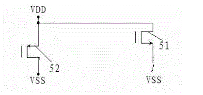
When an electrostatic voltage (ESD) is generated at the ground terminal or power supply terminal of the liquid crystal drive circuit, when the voltage at the ground terminal or power supply terminal of the liquid crystal drive circuit exceeds the threshold voltage of some NMOS switch tubes 51 or some PMOS switch tubes 52 , these NMOS switch tubes 51 Or the PMOS switch tube 52 is turned on, so that the electrostatic charge is effectively released, because not all the NMOS switch tubes 51 and all the PMOS switch tubes 52 are turned on together, reducing the effectiveness of the protection circuit

Method used


Image

  • Protection circuit for liquid crystal driver circuit
  • Protection circuit for liquid crystal driver circuit

Examples


Embodiment Construction

[0009] see figure 1 In order to better understand the technical solution of the present invention, the inventors of the present invention will describe in detail below through specific embodiments in conjunction with the accompanying drawings:

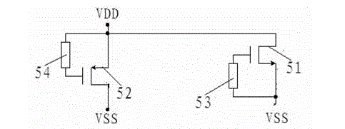
[0010] A protection circuit for a liquid crystal drive circuit of the present invention is located between the ground terminal (VSS) and the power supply terminal (VDD) of the liquid crystal drive circuit, including N NMOS switch tubes 51 and N PMOS switch tubes 52, each NMOS The source of the switching tube 51 is connected to the ground terminal of the liquid crystal driving circuit, the drain is connected to the power supply terminal of the liquid crystal driving circuit, the source of each PMOS switching tube 52 is connected to the power supply terminal of the liquid crystal driving circuit, and the drain is connected to the ground terminal of the liquid crystal driving circuit A first parallel resistor 53 is provided between the so...


PUM


Abstract

The invention discloses a protection circuit for a liquid crystal driver circuit and belongs to the field of a smart power grid. The protection circuit comprises N NMOS (N-channel metal oxide semiconductor) switch tubes and N PMOS (P-channel metal oxide semiconductor) switch tubes, wherein the source of each NMOS switch tube is connected with the ground terminal of the liquid crystal driver circuit, the drain of each NMOS switch tube is connected with the power source end of the liquid crystal driver circuit, the source of each PMOS switch tube is connected with the power source end of the liquid crystal driver circuit, the drain of each PMOS switch tube is connected with the ground terminal of the liquid crystal driver circuit, a first parallel resistor is arranged between the source and the grid of each NMOS switch tube, and a second parallel resistor is arranged between the grid and the source of each PMOS switch tube. The protection circuit for the liquid crystal driver circuit has the technical effects that when static voltage is generated at the ground terminal or the power source end of the liquid crystal driver circuit, all the NMOS switch tubes and the PMOS switch tubes of the protection circuit are switched on simultaneously, so that the effectiveness of the protection circuit is accordingly improved.

Description

technical field [0001] The invention relates to a protection circuit for a liquid crystal drive circuit in the field of smart grids. Background technique [0002] The protection circuit is located between the ground terminal (VSS) and the power supply terminal (VDD) of the liquid crystal driving circuit. The function of the protection circuit is to release the electrostatic charge in time when the ground terminal or the power supply terminal of the liquid crystal drive circuit generates static voltage, so as to protect the safe operation of the liquid crystal drive circuit. Current protection circuits such as figure 1 As shown, it includes N NMOS switch tubes 51 and N PMOS switch tubes 52. The source of each NMOS switch tube 51 is connected to the ground terminal of the liquid crystal drive circuit, and the drain is connected to the power supply terminal of the liquid crystal drive circuit. Each PMOS switch tube The source of 52 is connected to the power terminal of the li...

Claims


Application Information

Patent Timeline
Patent Type & Authority Applications(China)
IPC IPC(8): G09G3/36H02H9/04
Inventor 聂纪平
Owner SHANGHAI BEILING
Why Eureka
Eureka Blog
Learn More