
Diode packaging equipment

A technology for packaging equipment and diodes, applied in electrical components, semiconductor/solid-state device manufacturing, circuits, etc., to solve problems such as inconsistent placement, worker influence, and high human resource consumption, reducing manual intervention, stabilizing processing efficiency, The effect of improving processing efficiency

Active Publication Date: 2013-06-12
SUZHOU ACCURACY ASSEMBLY AUTOMATION CO LTD
View PDF6 Cites 11 Cited by
  • Summary
  • Abstract
  • Description
  • Claims
  • Application Information

AI Technical Summary

Problems solved by technology

[0006] First and most importantly, in traditional manual operations, using a rocking plate for die bonding or manual lamination will cause potential hidden damage to the die. It is also difficult to be noticed or detected. After this kind of hidden damage is brought into the finished product of the diode, it will inevitably affect the overall quality and service life of the diode, and affect the finished product of the diode. In addition, the step-by-step manual work will affect the The consistency of the finished product will affect the quality of the finished product, such as the inconsistency of the placement of the crystal grains, etc., which will cause differences in the finished diode products of the same batch. This difference will also directly affect the downstream products. The problem of consistency in the two steps of chip dispensing and crystal bonding, but in the final step of laminating the upper sheet, it still needs to be done manually or by other equipment, and the problem of consistency still exists;
[0007] Secondly, the traditional manual work method requires at least 3-4 people to do the work, even if a die bonder is used to assist the work, at least 2-3 people are needed to do the work, so it consumes a lot of human resources; On the one hand, in today's increasingly bullish labor costs and labor shortages, many companies are trying their best to reduce the number of workers to control the cost of the company or ensure the normal production of the company. The above-mentioned operation methods are obviously difficult to meet the needs of the company; on the other hand On the one hand, the production efficiency of manual or semi-manual operation is obviously not high, and the emotional level of workers will inevitably affect their work, making the processing efficiency unstable;
[0008] Finally, with the development trend of miniaturization of various types of equipment, diodes are also increasingly miniaturized, so their chips are also being processed smaller and smaller. Traditional manual or semi-manual methods are not suitable for larger chips. It can still be operated, but for small chips, the difficulty of the operation will become higher, and the quality of the finished product will also appear due to the higher difficulty of the operation.

Method used


Image

  • Diode packaging equipment
  • Diode packaging equipment
  • Diode packaging equipment

Examples


Embodiment 1

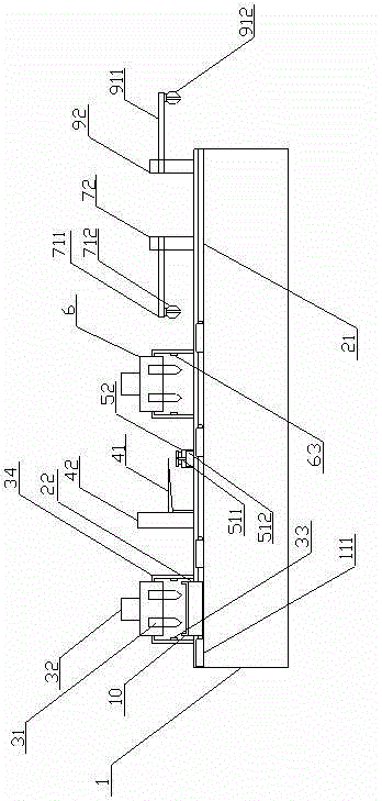
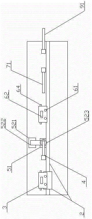
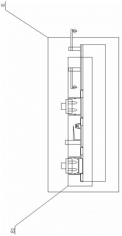
[0043] Such as figure 1 , figure 2 As shown, the diode packaging equipment in this embodiment includes: a machine base 1; a conveying mechanism 2, which is slidably connected to the machine base 1; a driving mechanism, which is arranged on the machine base 1, and is used to drive the conveying mechanism 2 to reach multiple station; the first dispensing mechanism 3, which is arranged on one end of the support 1, above the direction of movement of the conveying mechanism 2, the first dispensing mechanism 3 includes two first dispensing heads 31; the solid crystal mechanism 4, which It is arranged on the machine base 1 and above the moving direction of the conveying mechanism 2. The crystal-bonding mechanism 4 includes a crystal-bonding swing arm 41 and a swing-arm driving device 42 for driving the crystal-bonding swing arm 41. One end of the crystal-bonding swing arm 41 is also It is rotatably connected with the machine base 1, and the swing arm drive device 42 is implemented ...

Embodiment 2

[0059] Others are the same as those described in Embodiment 1, except that the swing arm driving device 42 is a decoupled direct drive device, which includes a rotary direct drive device, a linear direct drive device and a spline mechanism, and the spline The mechanism includes a spline shaft (or external spline) and a spline nut (or internal spline), and the rotating part of the rotary direct drive device is connected to the spline shaft with one of the linear moving parts of the linear direct drive device And move synchronously, the other one is connected with the spline nut and moves synchronously.

[0060] The working principle of the present invention is introduced below:

[0061] Place the lower material of the diode on the conveying mechanism 2, driven by the driving mechanism, the conveying mechanism 2 transports the lower material to the station of the first dispensing mechanism 3 for dispensing, and the dispensing is completed The unloading sheet continues to be tra...


PUM


Abstract

The invention discloses diode packaging equipment, which comprises a machine seat, at least one conveying mechanism, a driving mechanism, a first dispensing mechanism, at least one wafer fixing mechanism, at least one wafer supply mechanism, a second dispensing mechanism and at least one manipulator mechanism, wherein the conveying mechanism is slidingly connected with the machine seat, the driving mechanism is arranged on the machine seat, the first dispensing mechanism is arranged at one end of the machine seat and is positioned above the movement direction of the conveying mechanism, the wafer fixing mechanism is arranged on the machine seat and is positioned above the movement direction of the conveying mechanism, the wafer supply mechanism is arranged on the machine seat and is positioned at one side of the wafer fixing mechanism, the wafer supply mechanism comprises an ejection mechanism and a wafer fetching movement mechanism, the second dispensing mechanism is arranged on the machine seat and is positioned above the movement direction of the conveying mechanism, the manipulator mechanism is slidingly and / or rotatably connected with the machine seat, and the first dispensing mechanism, the wafer fixing mechanism, the second dispensing mechanism and the manipulator mechanism are sequentially arranged along the movement direction of the conveying mechanism. The diode packaging equipment has the advantages that the hidden damage of a diode is reduced, the uniformity of the finished products of the diode is improved, the processing efficiency is improved, and the diode packaging equipment is more suitable for miniature diode chips.

Description

technical field [0001] The invention relates to the technical field of semiconductor packaging, in particular to a diode packaging device. Background technique [0002] In the packaging process of the diode, it is a very important process to attach the chip between the upper and lower material sheets of the diode. [0003] Traditionally, the realization of this process is mostly realized by manual or semi-manual methods. The specific implementation method is: the first worker uses a glue dispenser to dispense glue on the lower material, and then moves the lower material that has been dispensed to the next worker. Sieve the crystal grains (that is, chips) to the dispensing position of the lower material through the shaking plate to complete the crystal bonding, and then move the semi-finished product after the crystal bonding to the next worker, who then uses the glue dispenser on the upper material. Do glue dispensing, and then attach the upper material sheet to the finish...

Claims


Application Information

Patent Timeline
IPC IPC(8): H01L21/50H01L21/56H01L21/683
Inventor 王敕
Owner SUZHOU ACCURACY ASSEMBLY AUTOMATION CO LTD
Learn More