Cutter structure

A technology for cutting tools and milling cutters, applied in the field of tool structure, can solve problems such as increase, product defect rate, manufacturing cost, and influence on the qualified rate of processed products.

Inactive Publication Date: 2013-06-19
泳捷科技有限公司
View PDF5 Cites 8 Cited by
  • Summary
  • Abstract
  • Description
  • Claims
  • Application Information

AI Technical Summary

Problems solved by technology

[0006] However, although this existing Chinese Taiwan Announcement No. 256128 "Drilling, Car Hole, Milling Simultaneous Chamfering and Trimming Device" that can be changed at will has the concept of two kinds of cutter combinations to process synchronously, the cutter of its chamfering is The sleeve and the bolt are locked on the drill bit, turning tool, milling cutter or tapping head. When drilling, turning, milling or tapping, etc., vibration will be generated. After a period of use, the lock on the The chamfering tool of the drill bit, turning tool, milling cutter or tapping head will loosen, which will affect the qualified rate of the processed product. Therefore, it is necessary to perform tool calibration every time during construction. In this way, the processing accuracy will also be improved. Disadvantages such as poor and increased processing hours, and the Chinese Taiwan Announcement No. 256128 "Drilling, turning, milling and chamfering, trimming device that can be changed at will" is only limited to drilling, turning, and milling in implementation. Or double-effect ...

Method used


Image

  • Cutter structure
  • Cutter structure
  • Cutter structure

Examples


Embodiment Construction

[0024] In order to have a more complete and clear disclosure of the technical means, the purpose of the invention, and the achieved effects of the present invention, a detailed description is given below, and please refer to the accompanying drawings and component numbers.

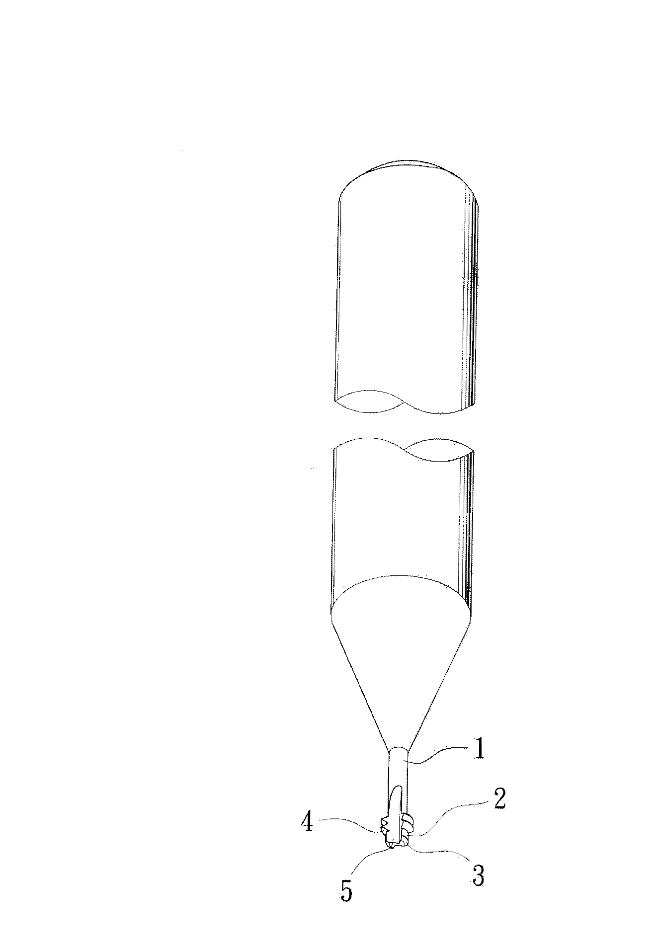
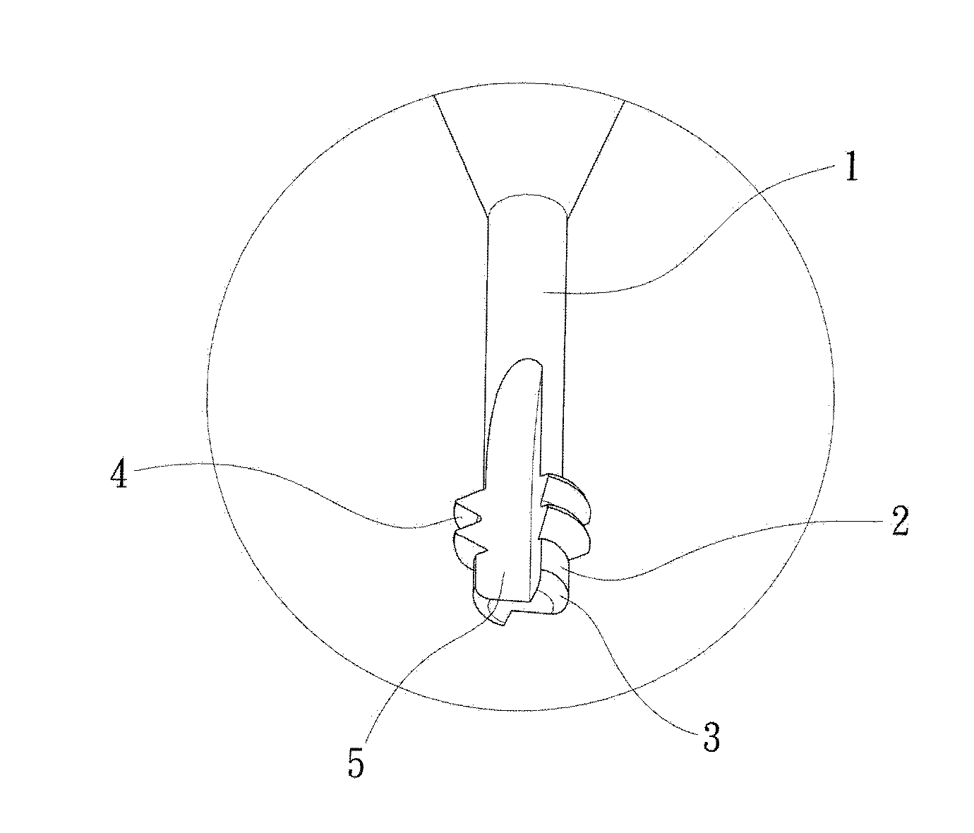
[0025] First, see figure 1 , figure 2 Shown, be the cutter structure of the present invention, be provided with cutter main body 1, and be provided with milling cutter part 2 on cutter main body 1, be formed with chamfering part 3 at the peripheral edge of milling cutter part 2 front end again, and make cutter main body 1 continue The thread cutter part 4 is formed after the milling cutter part 2 , and the chip removal groove 5 is formed extending from the milling cutter part 2 to the thread cutter part 4 .

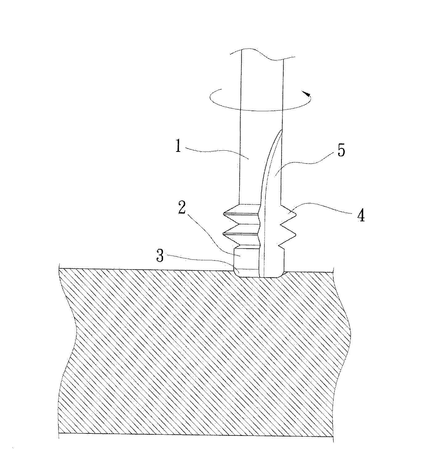
[0026] According to this, when processing such as threaded holes, the cutting tool of the present invention is installed on the CNC machine tool, so that after the CNC machine tool inputs the data s...


PUM


Abstract

The invention relates to a cutter structure which comprises a cutter main body. A milling cutter portion is arranged on the cutter main body, a chamfering portion is formed on the peripheral edge at the front end of the milling cutter portion, and a thread cutter portion is formed on the cutter main body and located behind the milling cutter portion in a connected mode. Therefore, the chamfering portion in the front of the cutter main body is utilized for achieving an equidistant chamfering function through numerical control, then a numerically-controlled spiral curve equation is utilized for driving a cutter edge of the milling cutter portion to mill a bottom hole, and lastly, the thread cutting portion is used for carrying out a thread milling process continuously, so that forming operation of a threaded hole can be finished once. During implementation, working hours consumed for changing cutters cumbersomely in a machining process can be effectively reduced, errors generated due to recalibration when the cutters are changed for multiple times can be prevented, the cost burden for purchasing the multiple cutters and machine tools can be further avoided, and more specifically, the competitiveness of the present manufacturing industry can be improved, and other substantive benefits can be increased.

Description

technical field [0001] The invention relates to a tool structure, especially a tool structure that can effectively save processing time, improve product qualification rate, and reduce manufacturing cost burden. Background technique [0002] The manufacturing industry is the hub of a country's industrial development. The manufacturing of many products depends on the manufacturing and forming of cutting tools, such as: turning tools, milling cutters, boring tools, taps, drills, etc. Different cutting tools have their own specific cutting tools. Function, and depending on the complexity of processing, product forming must rely on the combination of various cutting tools to form. [0003] For example: for the production of internal threaded holes, first use the positioning drill to perform chamfering and positioning holes on the processed object, then use the drill bit to drill the positioning holes, and then use the tap to tap along the drilled holes to facilitate the drilling....

Claims


Application Information

Patent Timeline
IPC IPC(8): B23C5/10B23G5/20
CPCB23G5/188
Inventor 廖述涌
Owner 泳捷科技有限公司
Why Eureka
Try Eureka