Band-type automatic net-changing device and drip irrigation zone producing method using band-type automatic net-changing device

A technology of automatic screen changing and heating device, which is applied in the field of belt automatic screen changing device and the drip irrigation belt formed by using it, can solve the problem of pulling off; Chinese patent was announced on May 4, 2011, the efficiency of changing the screen is low, The mesh belt is broken and other problems, so as to achieve the effect of easy automatic control, power saving and power demand reduction

Inactive Publication Date: 2013-06-19
XINJIANG TIANYE GRP
View PDF6 Cites 1 Cited by
  • Summary
  • Abstract
  • Description
  • Claims
  • Application Information

AI Technical Summary

Problems solved by technology

The Chinese patent announced the CN 2652644Y plastic melt filter screen changing device on November 3, 2004 and the Chinese patent announced the CN 201712164 U electric belt-type filter device for film blowing machine on January 19, 2011, both of which are passed The filter is forcibly pulled out from between the two templates under the action of external force. Due to the high material pressure on the filter itself, it is easy to break the filter; the Chinese patent announced CN 201816212 U machine head on May 4, 2011 Automatic screen changing device, a kind of machine head automatic screen changing device, inherent screen changer (2) in bracket (1), the left side of screen changer is provided with mesh belt box (3), on the mesh belt box (3) The mesh belt (4) passes through the through groove in the middle of the screen changer, and the water cooling coil (5) is arranged on both sides of the through groove on the right side of the screen changer, and the heating rod (6) and the thermocouple (7) are arranged on the inner side. ), water cooling coils (5) are arranged on both sides of the cavity on the other side of the through groove, and heating rods (8) and thermocouples (9) are arranged on the inner side. The heating rods and thermocouples are electrically connected to the electric control cabinet through wires, so It uses the twin-screw extruder head to extrude the plastic under high pressure to drive the mesh belt to move the mesh, but the extruder head and the mesh belt are vertically arranged, and there is no lateral thrust structure itself, and the pressure from the head is always perpendicular to the The mesh belt is not easy to produce lateral component force, so it is difficult to change the mesh, the efficiency of changing the mesh is low, and it is easy to break the mesh belt, resulting in failure; on June 8, 2005, CN 2703636Y announced the automatic Belt-type screen changer, an automatic belt-type screen changer for an extruder, is installed between the barrel of the extruder and the die head, including the injection barrel (1), the heating ring (2), the water inlet and outlet device ( 3), filter screen changer (4), filter screen plate (5), filter screen cylinder (11), filter screen (12), stainless steel heating pipe (13), heating ring (2) installed in the injection cylinder (1 ), one end of the injection cylinder (1) is connected to the die head, the other end is connected to the outlet end of the filter screen changer (4), and the inlet end of the filter screen changer (4) is connected to the screw barrel (9), The filter screen plate (5) is installed in the filter screen changer (4), and one end of the filter screen (12) is connected with the filter screen cylinder (11), and the other end passes through the filter screen plate (5) relative to the filter screen changer (4). ) surface of the inlet end of the filter screen changer (4) and positioned in the filter channel (14), the stainless steel heating tube (13) is installed in the corresponding heating part of the filter screen changer (4), the water inlet and outlet device ( 3) Connect with the corresponding part of the filter screen changer (4) to be cooled through the water pipe. The filter screen changer (4) consists of an inlet section (15), a working section (16), a sealing section (17) and an outlet section (18 ), between the inlet section (15) and the working section (16), between the working section (16) and the sealing section (17), and between the sealing section (17) and the outlet section (18) are respectively provided with heat-insulating recesses Groove (19), (20), (21), inlet section (15), stainless steel heating pipe (13) is all installed in the working section (16) and outlet section (18), inlet section (15), sealing section ( 17) are equipped with water inlet and outlet devices ( 3) The connected cooling water inlet and outlet holes (22) adopt a symmetrical circular feed and discharge channel structure. The feed of this structure has a greater impact on the filter screen, and the filter screen bears a large pressure and resistance. The required power consumption will also increase, and most of the sealing channels adopt a parallel structure, which has greater resistance to the flow of raw materials

Method used


Image

  • Band-type automatic net-changing device and drip irrigation zone producing method using band-type automatic net-changing device
  • Band-type automatic net-changing device and drip irrigation zone producing method using band-type automatic net-changing device
  • Band-type automatic net-changing device and drip irrigation zone producing method using band-type automatic net-changing device

Examples


Embodiment Construction

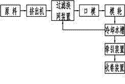
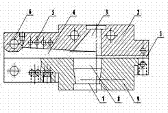
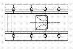
[0034] Refer to attached figure 1, Embodiment 1: a mesh belt type automatic screen changing device, including a screen changing plate 2 and a fixed plate 9 and the two are movably connected and form a sealing channel for the mesh belt to pass through at the joint, the screen changing plate and the fixed plate A heating device 6 and a cooling device 5 are provided, a pressure sensor is also provided on the screen changer, a discharge channel 7 communicating with the sealing channel 4 is provided on the fixed plate, a perforated plate 8 is provided at the outlet of the discharge channel, and the fixed plate Connect the die, and the screen changer is provided with a feed channel that communicates with the sealing channel and generates lateral force along the direction of the sealing channel. The feed channel is a special-shaped round structure, and the side of the feed channel connected to the extruder It is a circular mouth, and the other side is a square mouth. A bus line on th...


PUM


Abstract

The invention discloses a band-type automatic net-changing device and a drip irrigation zone producing method using the band-type automatic net-changing device. The device comprises a net-changing plate and a fixed plate, wherein the net-changing plate and the fixed plate are connected in a movable mode, a sealing channel used for bands to pass is formed at the connecting position, a heating device and a cooling device are arranged on the net-changing plate and the fixed plate, a pressure sensor is arranged on the net-changing plate, a discharging channel is arranged on the fixed plate and is communicated with the sealing channel, a multi-hole plate is arranged at an outlet of the discharging channel, a die is connected with the fixed plate, a feeding channel is arranged on the net-changing plate, is communicated with the sealing channel and produces a lateral component force along the direction of the sealing channel, and the sealing channel is a wedge-shaped cavity along the central line of the feeding channel and becoming from shallow to deep outward. When melting materials enter the feeding channel of the net-changing plate through an extruding machine, a generation line of the side wall of the channel is vertical to a circular plane, and the side wall of the channel stops expansion of melting bodies and enables part of the melting materials to move fast along the expanding channel and enter the sealing channel. When impurities of the sealing channel are few and pressure of the melting bodies is small, the cooling device opens and lowers temperature of the front end of the melting materials to enable the front end of the melting materials to solidify, the melting materials enter the discharging channel through the bands and the multi-hole plate, the discharging channel and the die are communicated, and the materials are sent to the die to be shaped.

Description

technical field [0001] The invention relates to a screen changing device, in particular to a belt-type automatic screen changing device and a drip irrigation belt production method formed by the device. Background technique [0002] In order to ensure the normal operation of the extruder, the extrusion screen changer is one of the key components. Its function is to make the melt extruded by the extruder pass through the filter and the diversion of the perforated plate, so that the rotary motion becomes Outflow in a straight line ensures that the melt can flow into the die of the extruder stably and evenly, thereby ensuring the quality of the product. In addition, the resin used in the extruder will inevitably produce some impurities in the process of production, transportation, storage, and production. These impurities are not allowed to enter the product. Therefore, the filter screen plays a role in filtering out impurities. role. The Chinese patent announced the CN 26526...

Claims


Application Information

Patent Timeline
Patent Type & Authority Applications(China)
IPC IPC(8): B29C47/08B29C47/68
Inventor 郭庆人李双全杨铭万锡涛严格李建清徐涛潘存明魏妍丽丁国军
Owner XINJIANG TIANYE GRP
Why Eureka
Try Eureka