Aerospace motor-driven helicopter

A helicopter and electric technology, applied in aircraft parts, power plant types, aircraft power transmission and other directions, can solve the problems of poor maneuverability, non-repeatable flight, complex energy consumption, etc., to achieve auxiliary uninterrupted driving, more conducive to manual control, increase The effect of wing strength

Inactive Publication Date: 2013-06-19
陆华扬
View PDF5 Cites 5 Cited by
  • Summary
  • Abstract
  • Description
  • Claims
  • Application Information

AI Technical Summary

Problems solved by technology

[0002] Existing helicopters use complex energy-consuming engines to drive the propellers to rotate at high speeds to achieve ascent. Complex energy-consuming, labor-intensive, high-strength wings, slow speeds, and low flight altitudes cannot fly in space like a spacecraft, and the launch of a spacecraft Lifting into the sky requires a huge rocket to propel it, which wastes energy, is unsafe, has high pilot requirements, is uncomfortable, has poor maneuverability, and cannot fly repeatedly and at low altitudes like an airplane, which is unfavorable for control, and an airplane cannot be like a spaceship. flying in space

Method used


Image

  • Aerospace motor-driven helicopter
  • Aerospace motor-driven helicopter
  • Aerospace motor-driven helicopter

Examples


Embodiment 2

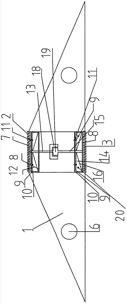
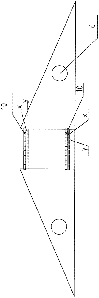
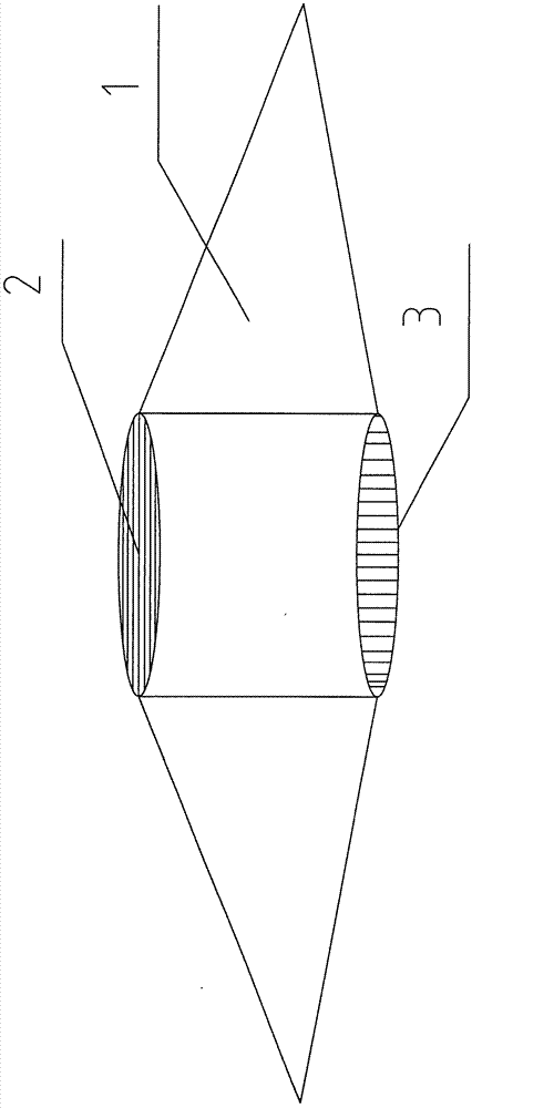
[0022] The auxiliary power of the present invention and embodiment 1 is: dish-shaped body, hollow column upper forward rotation screw propeller 12 and bottom reverse rotation screw propeller 14, the permanent magnet or electromagnet 9 of each wing top a little part and corresponding hollow The electromagnet winding on the column wall, through the power supply contact ABBA and the hollow column wall receiving the electric contact strip XY, after the two groups are energized, the same pole repels the different poles and attracts each other to push forward. The principle is: the power passes through the wing to make the top of the wing slightly The magnet or electromagnet winding 9 produces constant magnetic poles, and then through the permanent magnet or the four power supply contacts ABBA with different positive and negative poles at the bottom of the electromagnet 9 and the corresponding two sets of electric receiving contacts independent of the electromagnet winding of the corr...

Embodiment 3

[0024] The auxiliary power of the present invention and embodiment 2 is: body hollow column internal propeller 12, fixed frame 7 above 14 is equipped with reinforcing ring 11, electromagnet winding 10 and electric contact bar XY are arranged below reinforcing ring 11, wing and There are permanent magnets or electromagnets 9 and power supply contacts ABBA at the corresponding places of the reinforcement ring, through which two groups of power supply contacts ABBA with different positive and negative poles are energized with the electric contact strips XY of the two sets of electromagnet windings on the reinforcement ring respectively. These two groups of electromagnet windings 10, energized variable magnetic pole and permanent magnet or the magnetic pole of electromagnet 9 are the same pole and different pole, produce thrust and suction to assist wing to push forward and increase the intensity of wing.

[0025] Embodiment 1 of the present invention, the power of the aerospace el...

Embodiment 5

[0027] Embodiment 1 of the present invention and the auxiliary power supply of the aerospace electric helicopter is that the lower end of the central shaft 15 of the upper forward-rotating propeller 12 in the hollow column of the body has a generator stator 18 that rotates forward together with it, and the rotor 19 is mounted on the lower propeller central shaft 15 The upper end of the rotor rotates in the opposite direction in the stator 18, and the generated current is transmitted to each wing circuit of the upper and lower propellers through the central shaft 15 to provide part of the power supply for the aircraft.


PUM


Abstract

The invention discloses an aerospace motor-driven helicopter which includes a dish airframe, and jet aeromotors which are arranged on both sides of the airframe. The center of the airframe is in a hollow cylindrical shape, and low-speed direction adjusting blades are arranged on the upper portion and the lower portion of a hollow cylinder. An annular drive system formed by an electromagnet coil is arranged on the wall of the hollow cylinder. Two groups of fixed frame centers are arranged on the upper portion of the hollow cylinder, wherein the two groups of the fixed frame centers are arranged on the upper portion and the lower portion of a propeller by a foreward propeller through an axis. The upper fixed frame is provided with an auxiliary drive stiffening ring, and a reversal propeller is arranged on the lower portion; two groups of fixed frame centers are arranged on the lower portion of the hollow cylinder, wherein the two groups of the fixed frame centers are arranged on the upper portion and the lower portion of the propeller by a reversal propeller through an axis. The auxiliary drive stiffening ring is arranged on the fixed frame on the upper portion of the propeller. In addition, a rocket jet engine mouth is arranged on the rear portion of a middle section of each wing of the lower reversal propeller in a horizontal mode. Multiple resistance-increasing lifting blades are arranged on the bottom surface of each wing and a contrarotating generator is arranged at the intersection position of the center shaft of the upper foreward propeller and the center shaft of the lower reverse propeller.

Description

Technical field: [0001] The invention relates to a military-civil dual-purpose aerospace electric helicopter Background technique: [0002] Existing helicopters use complex energy-consuming engines to drive the propellers to rotate at high speeds to achieve ascent. Complex energy-consuming, labor-intensive, high-strength wings, slow speeds, and low flight altitudes cannot fly in space like a spacecraft, and the launch of a spacecraft Lifting into the sky requires a huge rocket to propel it, which wastes energy, is unsafe, requires high requirements for pilots, is uncomfortable, has poor maneuverability, and cannot fly repeatedly and at low altitudes like an airplane, which is unfavorable for control, and an airplane cannot be like a spaceship. Fly in space. Invention content: [0003] In order to solve the above-mentioned problems, the present invention provides a new combined drive type aerospace electric helicopter with simple structure, ingenious design, flexible maneu...

Claims


Application Information

Patent Timeline
IPC IPC(8): B64D35/00B64D27/16
Inventor 陆华扬其他发明人请求不公开姓名
Owner 陆华扬
Why Eureka
Try Eureka