Mechanical shaft-forming method of shield cutterhead maintenance shaft in tunnel and underground construction

A shield cutter head and underground engineering technology, which is applied in tunnels, tunnel linings, underground chambers, etc., can solve problems such as increased construction costs and construction periods, high construction safety risks, and complicated construction techniques, achieving shortened construction periods, Reduce construction risk and facilitate construction

Active Publication Date: 2013-06-19
CHINA RAILWAY TUNNEL GROUP CO LTD
View PDF4 Cites 20 Cited by
  • Summary
  • Abstract
  • Description
  • Claims
  • Application Information

AI Technical Summary

Problems solved by technology

[0003] At present, the traditional working shaft construction method adopted at home and abroad, the construction site is large, the construction process is complicated, and often requires construction dewatering, pipeline relocation, long-term traffic diversion and other work, which greatly increases the construction cost and construction period. In addition, the traditional shaft The construction adopts manual excavation and is often accompanied by water-carrying operations. The construction site is surrounded by buildings, and the construction safety risk is very high.

Method used


Image

  • Mechanical shaft-forming method of shield cutterhead maintenance shaft in tunnel and underground construction
  • Mechanical shaft-forming method of shield cutterhead maintenance shaft in tunnel and underground construction
  • Mechanical shaft-forming method of shield cutterhead maintenance shaft in tunnel and underground construction

Examples


Embodiment Construction

[0028] Embodiment of the present invention is described in conjunction with accompanying drawing:

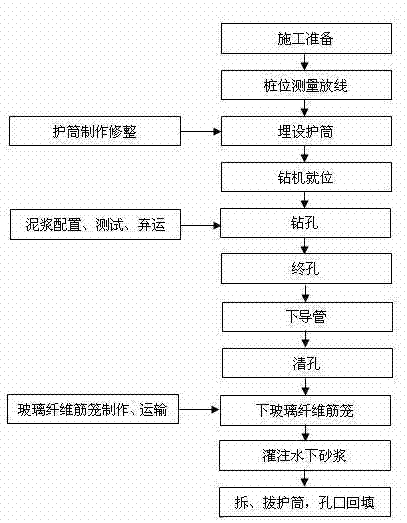
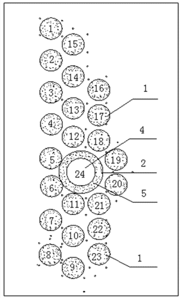
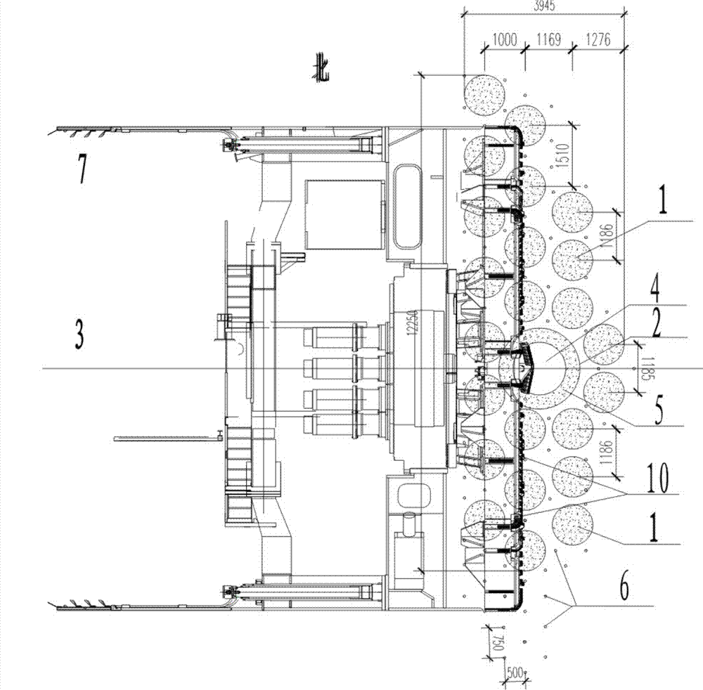
[0029] Such as figure 1 , 2 , 3, 4, and 5, a method for mechanical well-forming of shield cutter head maintenance well in tunnels and underground engineering, the steps are as follows:

[0030] 1) Firstly, at the position where the cutter head needs to be repaired in the shield tunnel, use geophysical prospecting and manual excavation to find out the underground pipeline (11) in the construction area, and mark the underground pipeline (11);

[0031] 2), and then carry out retreat grouting reinforcement on the 5m deep strata within the reinforcement range of bored piles,

[0032] 3), and then use the rotary drilling drill to construct 3 rows of φ1.0m glass fiber reinforced cast-in-place piles (1) in the reinforcement range of the shield tunnel with the pre-stop position as the center;

[0033] 4) Finally, on the tunnel axis (3) of the shield machine (6), a large-diameter (φ2.0...


PUM


Abstract

The invention relates to the technical field of shaft construction, and discloses a mechanical shaft-forming method of a shield cutterhead maintenance shaft in a tunnel and an underground construction. First, a position where a cutterhead needs maintenance in a shield tunnel is marked, and grouting reinforcement is conducted in a reinforcing range of bored cast-in place piles; then glass fiber cast-in-place piles (1) are adopted on a reinforcing range of the shield tunnel with the position of a pre-stop machine as the center; a cast-in-place pile (2) is constructed between pile groups on the tunnel axis (3) of a shield (6), then the shield cutterhead maintenance shaft (8) is formed by drilling of a hollow hole (4) in the middle of the cast-in-place pile (2) by a rotary-drill, and a steel pile casing is pre-buried at the mouth of the shield cutterhead maintenance shaft; then compensation grouting is conducted on a soil body stratum between the pile groups, finally a covered beam (9) is constructed on the top of the cast-in-place pile, and all the piles are connected in an integrated mode. The mechanical shaft-forming method of the shield cutterhead maintenance shaft in the tunnel and the underground construction is convenient to construct, rapid, safe, and capable of greatly reducing the number of excavation constructions, shortening a construction period and reducing construction cost and construction risks, and achieves the purpose that operation space is provided for shield cutterheads and shield cutters.

Description

technical field [0001] The invention relates to the technical field of shaft construction, and mainly relates to a method for mechanically forming a shield cutter head maintenance shaft in tunnels and underground engineering. Background technique [0002] In the urban underground railway tunnels and subway projects constructed by the shield method, due to the long-distance excavation of the shield machine, the poor adaptability of the cutterhead cutter and engineering geological conditions, etc., the cutterhead cutter is often worn and damaged seriously, so it is often necessary to install As a working shaft, the transformation and repair of the cutter head of the shield tunneling machine. To ensure the smooth progress of the project. [0003] At present, the traditional working shaft construction method adopted at home and abroad, the construction site is large, the construction process is complicated, and often requires construction dewatering, pipeline relocation, long-t...

Claims


Application Information

Patent Timeline
Patent Type & Authority Applications(China)
IPC IPC(8): E21D11/10E21D9/08
Inventor 许维清翟志国赵宝华杨志永张长强杨泽平
Owner CHINA RAILWAY TUNNEL GROUP CO LTD
Why Eureka
Try Eureka