recoil starter mechanism

A technology of starter and rotating shaft, applied in the direction of engine components, engine starting, machine/engine, etc., can solve problems such as safety problems and damaged parts, and achieve the effect of preventing damage and preventing the ratchet from immediately starting to swing.

Active Publication Date: 2016-05-11
STARTING IND CO LTD
View PDF6 Cites 0 Cited by
  • Summary
  • Abstract
  • Description
  • Claims
  • Application Information

AI Technical Summary

Problems solved by technology

Therefore, parts may be damaged and safety issues may occur

Method used


Image

  • recoil starter mechanism
  • recoil starter mechanism
  • recoil starter mechanism

Examples


Embodiment Construction

[0041] Embodiments will be described with reference to the drawings.

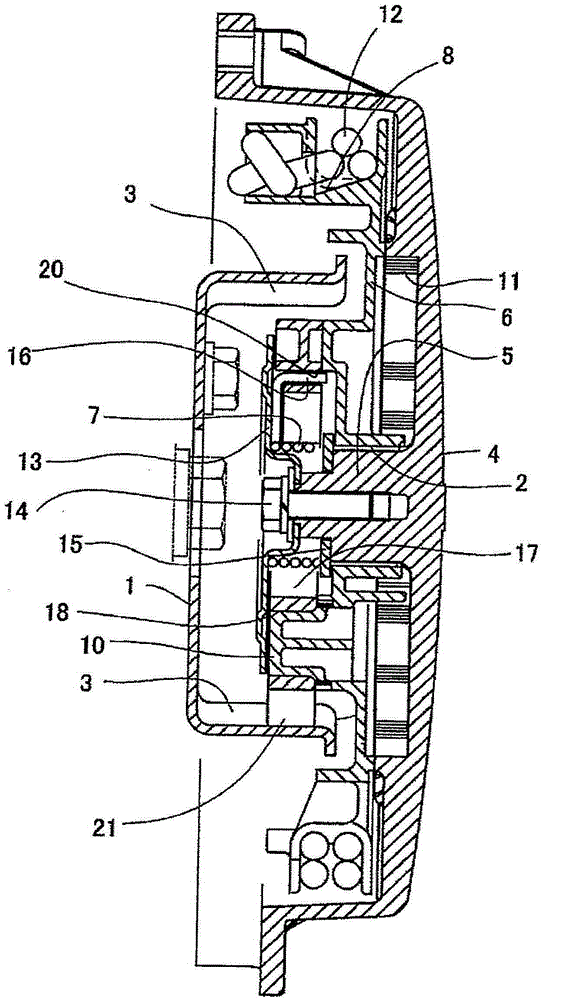
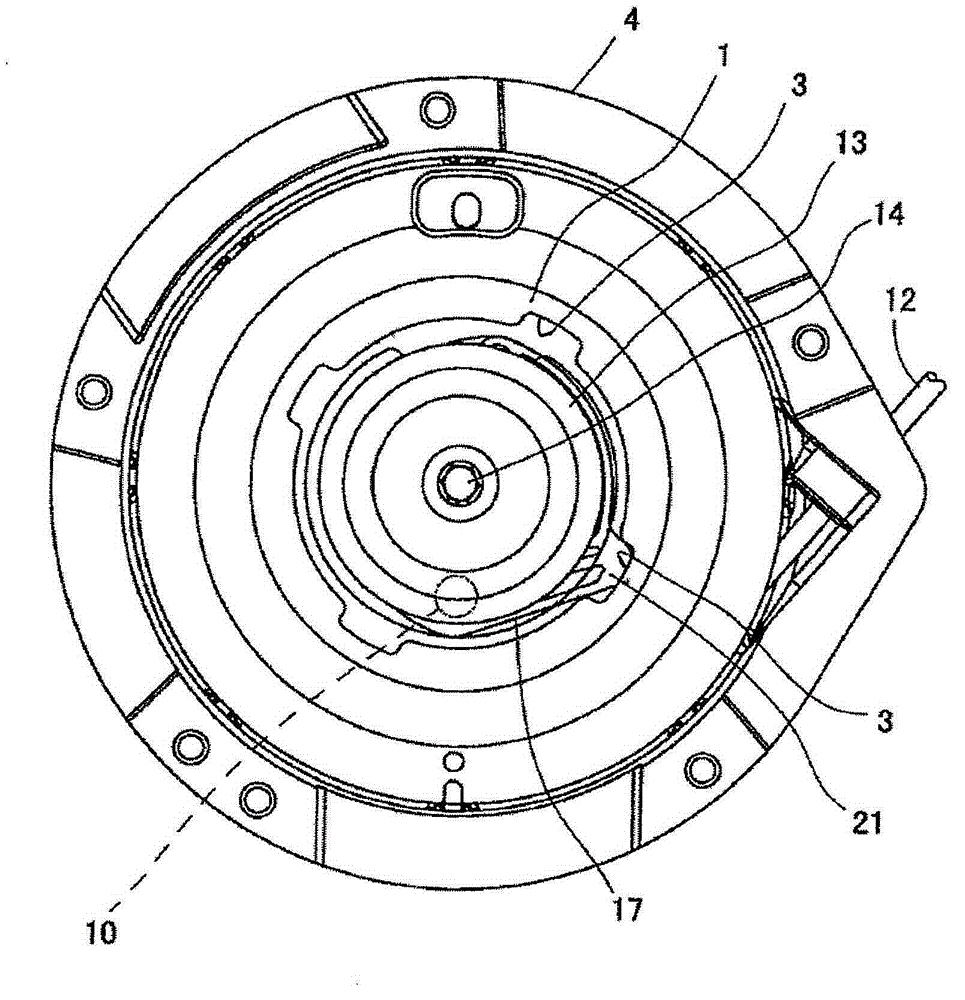
[0042] figure 1 Showing in section a recoil starter mechanism according to an embodiment, figure 2 The recoil starter mechanism is shown in operation from above, partly cut away.

[0043] The pulley 1 is directly coupled to, for example, the engine of a snowmobile. The engine and the pulley 1 rotate together with each other. The pulley 1 has a disk-like shape and includes a plurality of grooves (engagement portions) 3 formed in its inner peripheral surface. The rotation shaft 5 is provided inside the starter housing 4 and is provided at the center of the starter housing 4 . A rotatable rope drum 6 is rotatably mounted on the rotary shaft 5 , and a coil spring 7 is wound on the rotary shaft 5 .

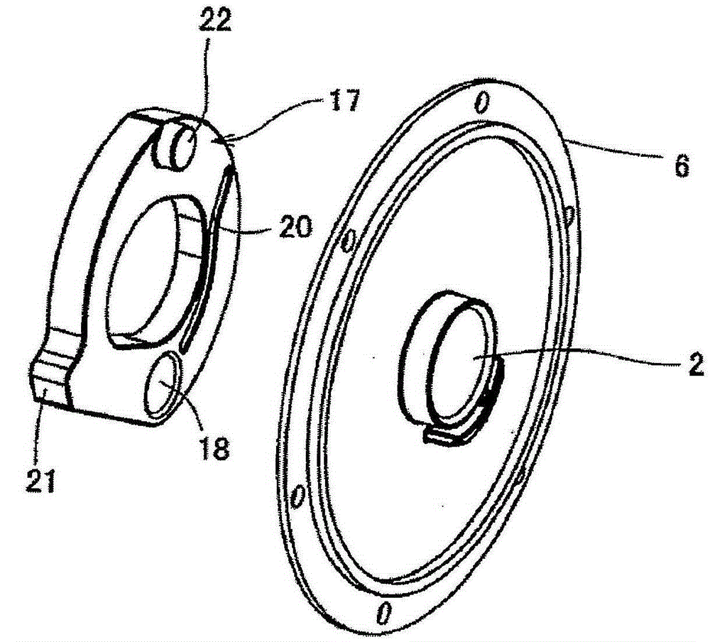
[0044] Such as Figures 1 to 4 As shown, the bearing hole 2 is formed in the rope drum 6 at a central portion of the rope drum 6 . The rope drum 6 includes: a rope winding groove 8 formed in an outer periphe...


PUM


Abstract

One embodiment provides a recoil starter mechanism comprising: a starter housing having a rotational shaft; a cord reel rotatably mounted on the rotational shaft; a coil spring, It is wound on the rotating shaft, and one end of the coil spring is formed as an end protrusion; a retaining plate, which retains the coil spring to the rotating shaft; and a ratchet, which is formed in a ring shape and is interposed between the rope drum and the retaining plate . The ratchet includes: a fulcrum around which the ratchet can swing relative to the rope reel; a guide groove in which a tip protrusion engages; and an engaging pawl to be engaged with an engaging portion of a pulley to thereby start the engine . The guide groove and the engagement claw are provided at opposite sides such that the rotation shaft is interposed between the guide groove and the engagement claw.

Description

[0001] Cross References to Related Applications [0002] This application claims priority from Japanese Patent Application JP2011-277354 filed on December 19, 2011, the entire contents of which are hereby incorporated by reference. technical field [0003] This invention relates to recoil starter mechanisms for small engines. Background technique [0004] For example, recoil starters are provided to small engines. The recoil starter comprises a spring for rewinding the rope on the rope drum by its restoring force. For example, in the recoil starter of JP-UM-S59-030217-B, the rope reel (4, corresponding to the reference numerals in JP-UM-S59-030217-B) is mounted in a rotatable manner On the rotating shaft (3) and the ratchet (10) is rotatably mounted on the rope drum (4). The ratchet (10) is rotatably mounted on the rope drum (4) at one end portion thereof, and the other end portion of the ratchet (10) is formed as an engagement pawl. When the rope (7) is pulled to start ...

Claims


Application Information

Patent Timeline
Patent Type & Authority Patents(China)
IPC IPC(8): F02N5/02
CPCF02N5/02F02N3/02
Inventor 松井聪木原太郎
Owner STARTING IND CO LTD
Why Eureka
Try Eureka