Light-emitting diode (LED) backlight module and electronic equipment

A backlight module and LED light source technology, which is applied in the field of backlight lighting, can solve the problems of large thickness of the direct-type LED backlight module, light shadows formed by LED light sources, and low LED arrangement density, so as to avoid areas that cannot be illuminated and reduce The effect of mixing light distance and reducing thickness

Inactive Publication Date: 2013-06-19
HISENSE VISUAL TECH CO LTD
View PDF6 Cites 1 Cited by
  • Summary
  • Abstract
  • Description
  • Claims
  • Application Information

AI Technical Summary

Problems solved by technology

With the continuous development of LEDs, their power is getting higher and higher. Under the same brightness requirements, the LED arrangement density becomes smaller, which leads to an increasing spacing P between LED lights. In order to keep the H / P ratio above When it is above a fixed value, the value of the light mixing distance H must be increased. In this way, if the light mixing distance H value becomes larger, the thickness of the direct-type LED backlight module will be larger
[0012] Since the light-emitting surface of the LED in the direct-lit LED backlight module in the prior art is parallel to the main reflector, that is, the light emitted by the LED light source will directly irradiate the diffuser plate, because the LED light source has a certain light-emitting angle , the irradiated area can only be a fixed area, which will lead to the technical problem that the area that the LED light source cannot irradiate will form light shadows

Method used


Image

  • Light-emitting diode (LED) backlight module and electronic equipment
  • Light-emitting diode (LED) backlight module and electronic equipment
  • Light-emitting diode (LED) backlight module and electronic equipment

Examples


Embodiment 1

[0062] Embodiment 1 of the present application provides a direct-type LED backlight module, the direct-type LED backlight module includes:

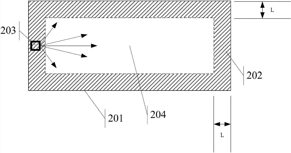
[0063] Please refer to Figure 2a and Figure 2b ,in, Figure 2a is the top view of the direct-lit LED backlight module, in Figure 2a The direct type LED backlight module includes a main reflector 201, which is divided into an edge area 202 and a central area 204, a first LED light source 203, and the first LED light source 203 is placed on the edge area of ​​the main reflector 201 202, wherein the edge area 202 of the main reflector 201 is an area whose distance from the edge of the main reflector 201 is less than or equal to the first preset distance L, in Figure 2a The shaded area in is the edge area 202, and the size of the edge area 202 depends on the size of the first preset distance L.

[0064] In addition, the position processing of the first LED light source 203 can be Figure 2a In addition to the position in the present ...

Embodiment 2

[0093] Based on the same inventive concept, Embodiment 2 of this application provides a display device, please refer to Figure 10 , the TV specifically includes the following structure:

[0094] Chassis 111;

[0095] a processor 112, arranged in the casing 111;

[0096] The display unit 113 is arranged on the casing 111 and connected to the processor 112, wherein the display unit 113 includes:

[0097] LCD panel 114;

[0098] The direct type LED backlight module introduced in Embodiment 1 of the present application is arranged at the bottom of the liquid crystal panel 114 , and the liquid crystal panel 114 can be provided with uniform light through the direct type LED backlight module.

Embodiment 3

[0100] Based on the same inventive concept, the embodiment of the present application also provides an electronic device, and the electronic device specifically includes the following structure:

[0101] chassis;

[0102] a processor disposed within the housing;

[0103] A display unit is arranged on the casing and connected to the processor, wherein the display unit includes:

[0104] LCD panel;

[0105] The above-mentioned direct type LED backlight module is arranged at the bottom of the liquid crystal panel, and uniform light can be provided to the liquid crystal panel through the LED backlight module.


PUM

PropertyMeasurementUnit
transmittivityaaaaaaaaaa

Abstract

The invention discloses a light-emitting diode (LED) backlight module and a television. The LED backlight module comprises a main reflecting piece, a first LED light source and a diffusion plate. A reflecting thin membrane is arranged on a first surface of the main reflecting piece. The main reflecting piece comprises an edge area and a central area. The edge area is an area where the distance between the edge area and the edges of the main reflecting piece is less than or equal to a first preset distance. The first LED light source is arranged in the edge area. The first LED light source is an LED light source with first power. A light emitting surface of the first LED light source is perpendicular to the main reflecting piece. Light rays emitted by the light emitting surface light on the central area of the main reflecting piece. The diffusion plate is arranged above the first LED light source, and is parallel to the main reflecting piece. The light rays emitted through the light emitting surface of the first LED light source form scattered light after being reflected by the main reflecting piece and being reflected and refracted by the diffusion plate and light out of the diffusion plate.

Description

technical field [0001] The invention relates to the technical field of backlight lighting, in particular to an LED backlight module and electronic equipment. Background technique [0002] With the development of electronic technology, more and more electronic devices have been produced, among which, many electronic devices have liquid crystal display screens. Usually, liquid crystal display screens include liquid crystal panels and backlight modules. The liquid crystal panels are composed of two layers A liquid crystal layer is sandwiched between glass substrates. Since the liquid crystal panel itself does not emit light, a uniform light source system needs to be provided for it through the backlight module. [0003] In the prior art, generally, the LED backlight module includes: a direct-type LED backlight module and an edge-type LED backlight module, wherein, such as Figure 1a and Figure 1b As shown, the direct type LED backlight module includes the following structure ...

Claims


Application Information

Patent Timeline
Patent Type & Authority Applications(China)
IPC IPC(8): F21S8/00F21V19/00F21V13/04G02F1/13357F21Y101/02
Inventor 宋志成乔明胜
Owner HISENSE VISUAL TECH CO LTD
Why Eureka
Try Eureka