Metal-resistant super-high frequency radio frequency identification device (RFID) label

An RFID tag and ultra-high frequency technology, applied in the field of RFID electronic tags, can solve problems such as low reading efficiency, narrow bandwidth, and reduced communication distance, and achieve large receiving and radiating area, wide frequency bandwidth, and good stability Effect

Inactive Publication Date: 2013-06-19
江苏安智博电子科技有限公司
View PDF5 Cites 11 Cited by
  • Summary
  • Abstract
  • Description
  • Claims
  • Application Information

AI Technical Summary

Problems solved by technology

However, the problems of this barcode technology are: short reading distance, non-group reading, low reading efficiency, non-renewable information, and cannot be used in many special environments.
However, when it is pasted or installed on a metal surface, the metal greatly weakens the communication performance of the RFID tag, resulting in the problem that its reading distance is greatly reduced, such as Figure 9 As shown in (b), the root cause is that a current in the opposite direction to the dipole antenna surface current will be generated on the metal surface, which will cancel the electromagnetic field generated by the dipole antenna surface current; the second type is to make a dipole antenna When using a pole antenna, the distance from it to the metal surface is increased

Method used


Image

  • Metal-resistant super-high frequency radio frequency identification device (RFID) label
  • Metal-resistant super-high frequency radio frequency identification device (RFID) label
  • Metal-resistant super-high frequency radio frequency identification device (RFID) label

Examples


Embodiment Construction

[0042] structure

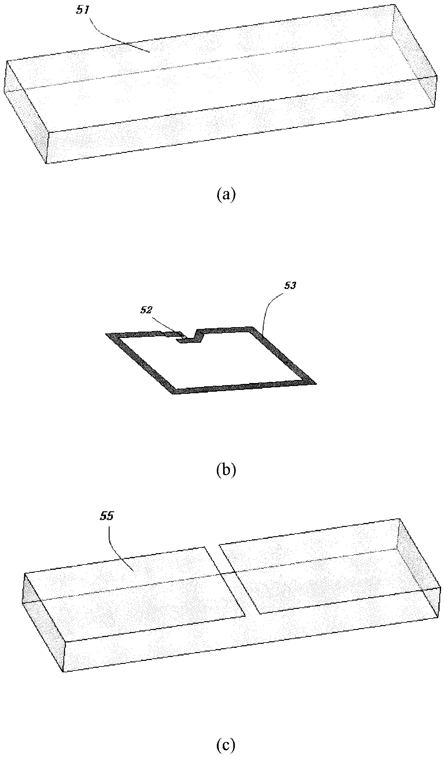
[0043] figure 1 It is a detailed three-dimensional exploded view of the RFID tag 50 of the present invention.

[0044] Such as figure 1 As shown in (a), the label dielectric member 51 is a dielectric plate with a size of 70x20x6mm.

[0045] Such as figure 1 As shown in (b), the integrated circuit chip 52 is mounted on the first loop antenna 53 to form a closed-loop near-field antenna; the first loop antenna is an etched antenna made of PET.

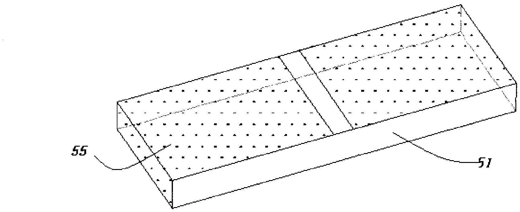
[0046] Such as figure 1 As shown in (c), the second loop antenna 55 is made of copper foil.

[0047] Such as figure 2 As shown, the second loop antenna 55 is attached to the label dielectric member 51 .

[0048] The label dielectric member 51 has, for example, a dielectric constant of 2.4, and can be formed using other inexpensive materials, such as a resin material with good formability.

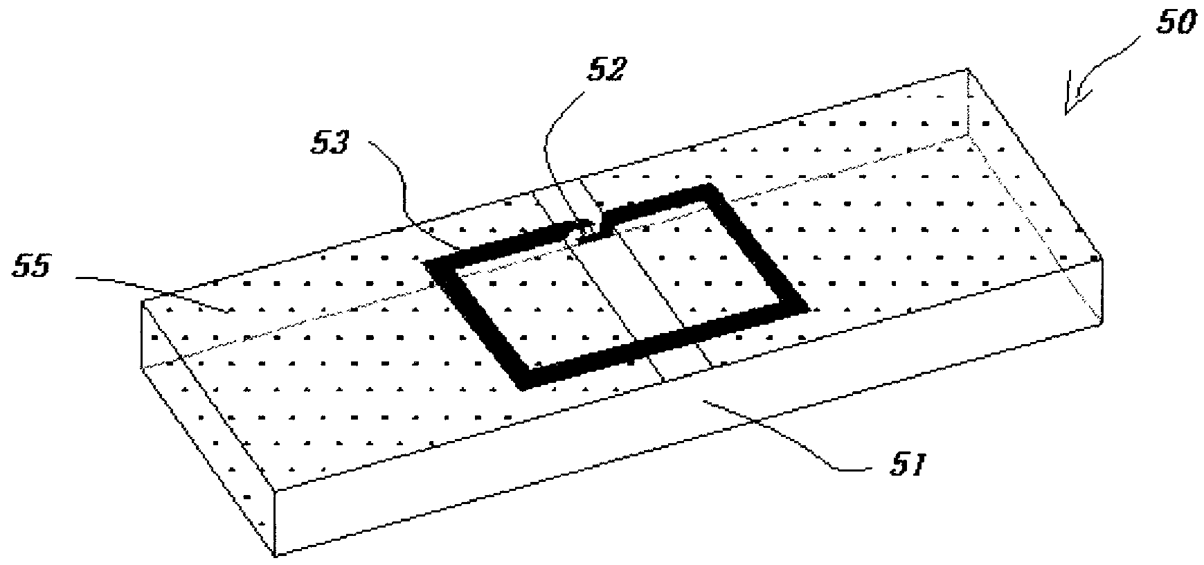
[0049] image 3 is a schematic diagram of an embodiment of the present invention after assembly, such as image 3 As...


PUM


Abstract

The invention provides a metal-resistant super-high frequency radio frequency identification device (RFID) label (50). The metal-resistant super-high frequency RFID label (50) comprises a label electric medium part (51), a first annular antenna image (53) and a second annular antenna image (55). The second annular antenna image (55) is continuous from a first surface of the label electronic medium part (51) to a second surface of the label electric medium part (51). And a fracture is formed in the first surface of the label electric medium part (51). The first annular antennal image (53) is located on the second annular antennal image (55) and connected with the second annular antennal image (55) in a couple mode without conducting electricity. An integrity circuit chip (52) is installed on the first annular antenna image (53).

Description

technical field [0001] The present invention relates to an RFID (radio frequency identification) electronic tag, in particular to an electronic tag that can be applied to the surface of a metal material or a non-metal material, and has the advantage of excellent reading distance when it is attached to a metal or non-metal. Background technique [0002] In logistics, asset management, and production operation management, the method of affixing printed barcodes to products or their packaging has been commonly used. However, the problems of this barcode technology are: short reading distance, non-group reading, low reading efficiency, non-renewable information, and cannot be used in many special environments. [0003] Therefore, the current RFID technology realizes the reading and writing of information in a non-contact manner, the reading distance is long, and the group reading function can be realized. It greatly improves the efficiency of reading and writing tags, and it can...

Claims


Application Information

Patent Timeline
IPC IPC(8): G06K19/077
Inventor 孙向荣
Owner 江苏安智博电子科技有限公司
Why Eureka
Try Eureka