A Low-Voltage Differential Signal Driver with Common-Mode Feedback

A low-voltage differential signal and signal driver technology, which is applied in the fields of logic circuit coupling/interface using field effect transistors, baseband system components, logic circuit connection/interface layout, etc. The problem of large die point resistance and large area occupied, to achieve the effect of simple bias circuit, less components, and avoiding area consumption

Active Publication Date: 2016-08-03
SOI MICRO CO LTD
View PDF2 Cites 0 Cited by
  • Summary
  • Abstract
  • Description
  • Claims
  • Application Information

AI Technical Summary

Problems solved by technology

[0005] The main purpose of the present invention is to provide a LVDS driver with common mode feedback to solve the problems of complex bias circuit, large power consumption and large area occupied by the large resistor for extracting the common mode point in the existing LVDS driver

Method used


Image

  • A Low-Voltage Differential Signal Driver with Common-Mode Feedback
  • A Low-Voltage Differential Signal Driver with Common-Mode Feedback
  • A Low-Voltage Differential Signal Driver with Common-Mode Feedback

Examples


Embodiment Construction

[0027] In order to make the object, technical solution and advantages of the present invention clearer, the present invention will be described in further detail below in conjunction with specific embodiments and with reference to the accompanying drawings.

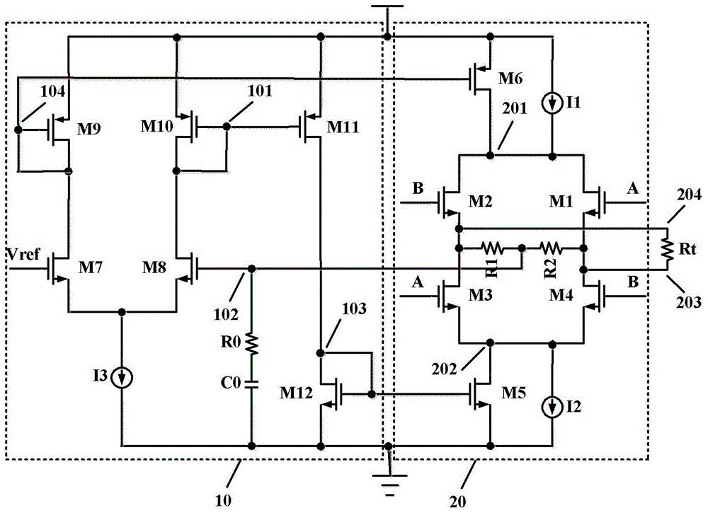
[0028] figure 1 It is a circuit schematic diagram of an LVDS driver with common-mode feedback in the prior art. The LVDS driver includes an amplifier, a negative feedback loop, a current bias and a driving circuit; wherein the single-stage circuit composed of M7-M10 and a current source I3 The differential amplifier is used to amplify the difference between the voltage at node 102 and the reference voltage Vref; the negative feedback loop composed of M5, M6, M11, M12, R1, and R2 is combined with the amplifier to stabilize the common mode of the output LVDS signal Voltage; current bias I1 and I2 provide a suitable bias current for the drive circuit; the drive circuit is used to generate LVDS signals.
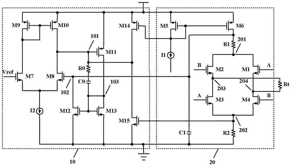
[0029] figure 2 ...


PUM


Abstract

The invention discloses a low voltage differential signal driver provided with common-mode feedback. The driver comprises a common-mode feedback circuit (10) and a driving circuit (20), wherein the common-mode feedback circuit (10) is used for stabilizing common-mode voltage of outputted low voltage differential signals, and the driving circuit (20) is sued used for generating the low voltage differential signals. The low voltage differential signal driver provided with common-mode feedback utilizes the mode of cancelling extraction of large resistance of common mode points, and achieves the low voltage differential signaling (LVDS) driver provided with the common-mode feedback. The driver is simple in biasing circuit, is improved in performances including power consumption, area and the like, and solves the problems that existing LVDS drivers are complicated in biasing circuit, large in power consumption and large in occupied area of the large resistance of the extracted common mode points.

Description

technical field [0001] The invention relates to the technical field of CMOS analog integrated circuit design, in particular to a Low-Voltage Differential Signaling (Low-Voltage Differential Signaling, LVDS) driver with common-mode feedback. Background technique [0002] The LVDS technology that appeared in the 1990s, as an interface technology with many advantages such as low power consumption, strong anti-interference ability, fast transmission speed, long transmission distance, and easy matching, can meet the application requirements of today's high-performance data transmission. It is a key technology to solve the bottleneck problem of data transmission. It was proposed by the National Semiconductor Corporation of the United States and is gradually becoming the focus of people's research. [0003] The main function of the LVDS driver is to convert TTL or CMOS signals into LVDS signals. At present, the working mode of the driver is divided into voltage mode and current mod...

Claims


Application Information

Patent Timeline
Patent Type & Authority Patents(China)
IPC IPC(8): H04L25/02H03K19/0185
Inventor 赵建中赵撼坤谢振博刘海南黑勇周玉梅
Owner SOI MICRO CO LTD
Why Eureka
Try Eureka