
Wig

A wig and hair technology, which is applied in the field of wigs, can solve problems such as staining, damage, and damage to the locking components, and achieve the effects of increasing lifespan, realizing lifespan, and preventing fatigue

Active Publication Date: 2013-06-26
ARTNATURE
View PDF15 Cites 5 Cited by
  • Summary
  • Abstract
  • Description
  • Claims
  • Application Information

AI Technical Summary

Problems solved by technology

[0020] Therefore, in the wigs of the above-mentioned patent documents 1 to 8, there is the following problem: when the wig is repeatedly worn and taken off many times, the locking member is stained or even damaged, and when the locking member is replaced each time, the peripheral edge of the wig base will be damaged. cause physical or chemical damage
Also, if the peripheral portion of the wig base is damaged, the wig is unusable even if the main body of the wig is still beautiful.
[0021] On the other hand, in the wigs of the above-mentioned Patent Documents 1 to 8, there is a problem that when the fixing of the own hair is released from the locking member, the adhesive is dissolved by the remover or the solidified adhesive is pulverized by pliers. So the own hair used in fixation is damaged
However, in the wigs of the aforementioned Patent Documents 1 to 8, there is a problem that the position of the adhesive and the double-sided tape attached to the peripheral portion of the wig base changes every time the fixed position of the own hair is changed, causing damage to the wig. The range of damage caused by the peripheral part of the base body is expanded
[0022] Furthermore, in the wigs of the aforementioned Patent Documents 1 to 8, there is a problem that, while the wearer is wearing the wig, the operation of dissolving the adhesive with a remover or crushing the cured adhesive with pliers is necessary to remove the wig. operability is poor

Method used


Image

  • Wig
  • Wig
  • Wig

Examples


change example 1

[0126] Such as Figure 12 As shown in (a), it is also possible to arrange a reinforcing sheet (or film) 40 made of synthetic resin or woven cloth on the outer periphery of the back of the wig base 10 made of a mesh member, and arrange the first rail member 13 through the reinforcing sheet 40 And the second rail member 14.

[0127] With such a structure, the outer periphery of the wig base 10 to which load is applied when the wig 1 is fixed can be reinforced, the durability of the wig base 10 can be improved, and the life of the wig 1 can be extended.

[0128] As the reinforcing sheet 40 , for example, a polyurethane sheet (or film) may be sewn or thermally welded to the mesh member of the wig base 10 . In addition, such a reinforcing sheet 40 is not an essential component of the present invention, and may be provided according to the strength of the peripheral portion of the wig base 10 . For example, when the reinforcing sheet 40 is not provided, it is also possible to rein...

change example 2

[0130] Such as Figure 12 As shown in (b), for example, a structure in which a plurality of linear recesses or protrusions 21 a , 21 a , 21 a . . . By providing such recesses or protrusions 21a, the frictional resistance of the transparent resin film 21 which is the adhesive surface of the locking member 20 can be increased, and the holding force of the adhesive to the wig 1 can be improved. In addition, the concave portion or the convex portion provided on the transparent resin film 21 is not limited to a linear shape, and may be a plurality of dot-shaped concave portions or convex portions.

change example 3

[0132] Such as Figure 12 As shown in (c), for example, a structure in which a plurality of minute protrusions 21 b , 21 b , 21 b . By providing such micro-protrusions 21b, when the self-hair 100 passing through the slit 24 is clamped by the adhesive surface of the locking member 20, the self-hair 100 is locked by a plurality of micro-protrusions 21b, 21b, 21b... ..., so that the retention force of the adhesive and the adhesive tape on the own hair 100 can be improved. The shape of the minute protrusion 21b is, for example, a hemispherical shape, a cylindrical shape, an approximately mushroom shape, a hook shape constituting one of the surface fasteners, or the like.


PUM


Abstract

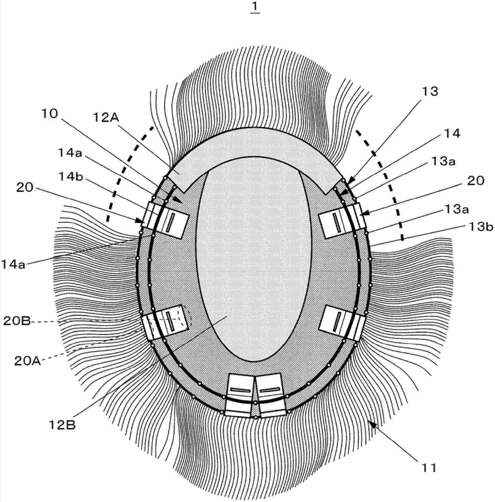
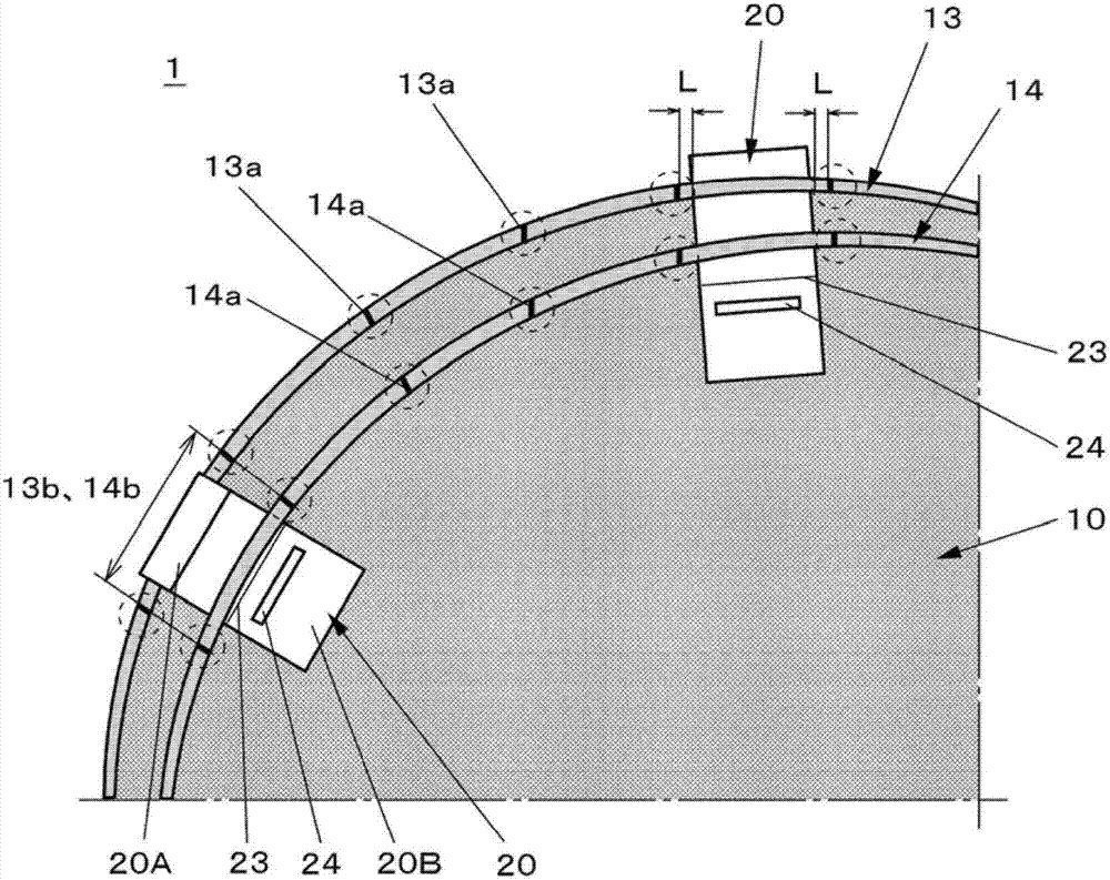
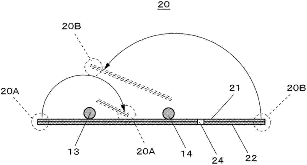
The invention provides a wig in a fixedly clamping structure. The wig rarely damages the wig matrix even through repeated wearing, moreover, the wig provided can reduce the burden applied on one's hair while the wig is detached and can high-efficiently perform the wearing operation of the wig. The wig is provided with two track members which are approximately and parallelly fixed on the periphery of the back surface of the wig matrix, and a fixedly clamping member having a slit for a wearer's hair to pass through, each track member is provided with more than two fixing parts at intervals, the part between the two fixing parts forms a non-fixing part relative to the wig matrix, one end side of the fixedly clamping member is fixed at the other track member, and the other end side of the fixedly clamping member penetrates through the non-fixing part of the track member and coils backwards. The other end side is bonded to one end side when the wearer's hair is clamped between the other end side and one end side of the fixedly clamping member after passing through the slit.

Description

technical field [0001] The present invention relates to a wig that is locked to the head by the wearer's own hair, and more particularly to a wig with a locking structure that causes minimal damage to the base of the wig even if it is repeatedly put on and taken off. Background technique [0002] Ordinary wigs can be divided into two types: long-term wear and short-term wear. Among them, long-wearing type wigs can be divided into self-hair fixation methods in which the wearer's own hair is locked to the head, and matrix bonding in which an adhesive is applied to the back of the wig base to adhere to the wearer's scalp. Way. On the other hand, short-term wearable wigs can be divided into two types: using a reverse-type stopper (hairpin) installed on the wig base to fix the wearer's own hair to the stopper method and using a double-sided stopper installed on the wig base. A double-sided tape method in which the tape sticks to the wearer's scalp. [0003] The long-wearing ty...

Claims


Application Information

Patent Timeline
Patent Type & Authority Applications(China)
IPC IPC(8): A41G3/00
Inventor 杉浦诚
Owner ARTNATURE
Learn More