Three-dimensional carving machine
A three-dimensional engraving machine and rack technology, applied in the field of engraving machines, can solve the problems of plant environment impact, easy accumulation, engraving machine damage, etc., and achieve the effects of reducing potential safety hazards, improving plant environment, and improving processing accuracy.
- Summary
- Abstract
- Description
- Claims
- Application Information
AI Technical Summary
Problems solved by technology
Method used
Image
Examples
Embodiment 1
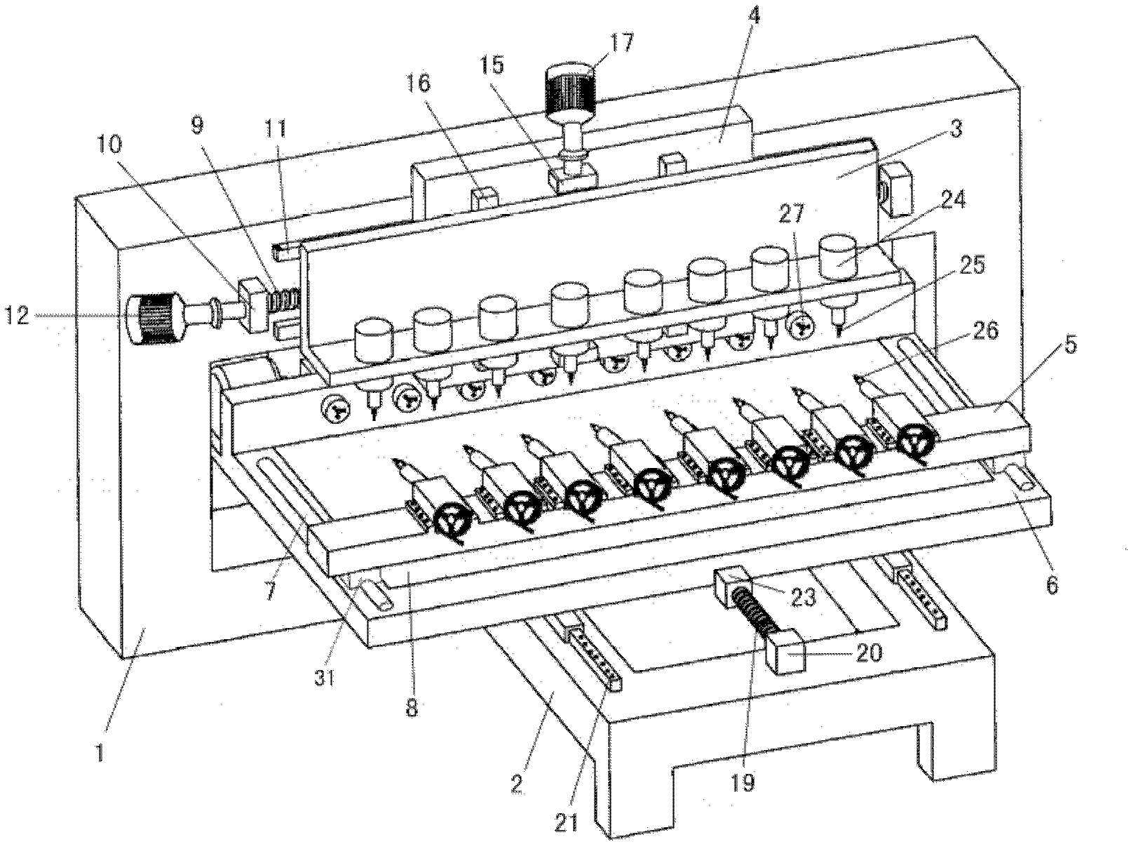
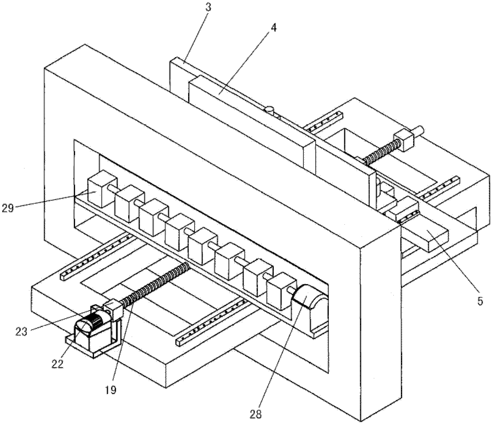
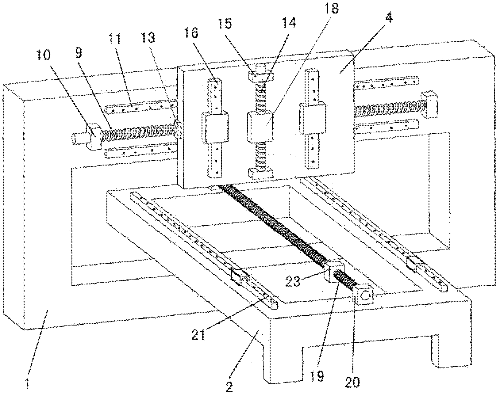
[0055] Please refer to Figure 1 to Figure 3 , the present invention provides a three-dimensional engraving machine, comprising a frame 1, a base 2, a tool holder 3, a horizontal support plate 4, a slat 5, a workbench 6 and a cylindrical guide rail 7, and a cutter 25 is arranged on the tool holder 3, The cylindrical guide rails 7 are arranged on both side edges of the workbench 6, the workbench 6 is fixed on the base 2 through a vertical movement mechanism, and the tool holder 3 is fixed on the horizontal support through a vertical movement mechanism On the plate 4, the horizontal support plate 4 is fixed on the frame 1 through a lateral movement mechanism, the slat 5 is slidably arranged on the cylindrical guide rail 7, and the workbench 6 is provided with a Debris baffle8.
[0056] The front side of described tool rest 3 is provided with the cutter 25 that is arranged in a straight line, and each cutter 25 is contained on the water-cooled high-speed motor 24 that is used to...
Embodiment 2
[0063] This embodiment is basically the same as Embodiment 1, the difference is that the baffle plate 8 is engaged with the workbench 6 at a certain angle, and there is a gap between the lower side of the baffle plate 8 and the workbench 6, and wood chips or dust accumulate on the It will automatically slide down to a certain extent, which is more convenient for cleaning. More preferably, a receiving device (not shown) is provided on the lower side of the workbench 6 baffle 8, and the wood chips or dust that slide off from the baffle can fall into the receiving device Unified processing.
Embodiment 3
[0065] This embodiment is basically the same as Embodiment 1, the difference is that, as Figure 4 As shown, the baffle plate 8 is a sheet made of annular canvas, rubber belt or other suitable materials (hereinafter referred to as annular canvas, etc.), and any opposite sides of the workbench 6 are fixedly equipped with rollers (30). The canvas and the like are set on the rollers 30 , and at least one roller 30 is driven to rotate by a motor, thereby driving the annular canvas and the like to perform circular motion. Wood chips or dust generated by the workpiece during the processing fall onto the annular canvas and the like and are transported to the outside of the workbench 6 along with its movement. More preferably, a receiving device is provided at the moving end of the circular canvas, etc., and the sawdust or dust that slides off the baffle can fall into the receiving device for unified treatment.
PUM
 Abstract
Description
Claims
Application Information
 - R&D
- Intellectual Property
- Life Sciences
- Materials
- Tech Scout
- Unparalleled Data Quality
- Higher Quality Content
- 60% Fewer Hallucinations
Browse by: Latest US Patents, China's latest patents, Technical Efficacy Thesaurus, Application Domain, Technology Topic, Popular Technical Reports.
© 2025 PatSnap. All rights reserved.Legal|Privacy policy|Modern Slavery Act Transparency Statement|Sitemap|About US| Contact US: help@patsnap.com


